LB1923M View Datasheet(PDF) - SANYO -> Panasonic
Part Name
Description
Manufacturer
LB1923M Datasheet PDF : 17 Pages
| |||
Continued from preceding page.
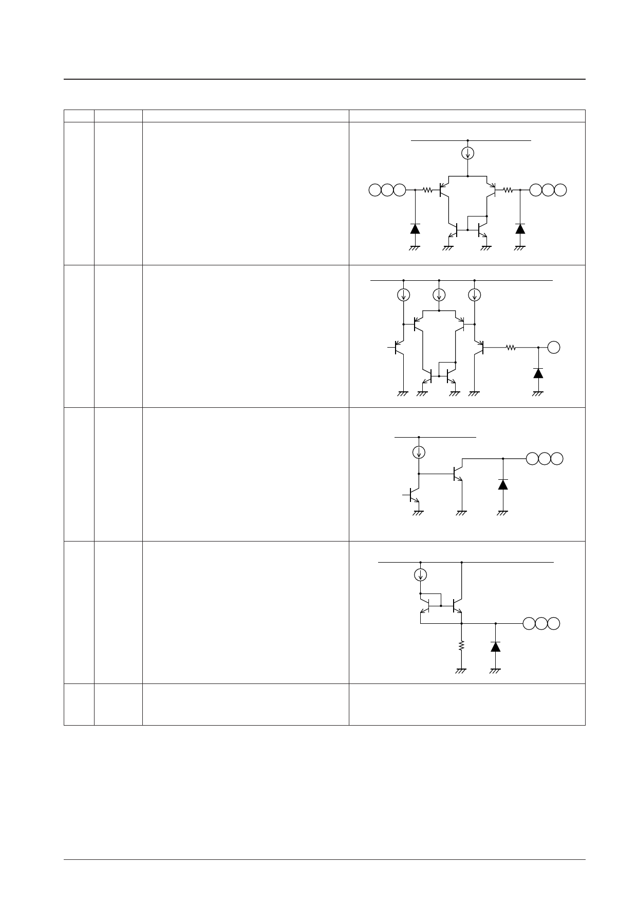
Pin No.
Pin
LB1923M
Functions
Equivalent circuit
VCC
19
IN1+
Hall inputs
20
21
IN1–
High is defined as IN+ > IN–, and low as the opposite.
IN2+
An amplitude of 100 mV p-p (differential) or more is
200 Ω
20 22 24
22
IN2–
desirable in the Hall signals. Connect capacitors between
23
IN3+
the IN+ and IN– pins if noise on the Hall signals causes
24
IN3–
problems.
200 Ω
19 21 23
VCC
Output current detection
Connect a resistor between this pin and ground.
25
RF
The output limitation maximum current, IOUT, is set to be
0.52/Rf by this resistor.
200 Ω
25
26
28
30
UL
VL
WL
This IC implements duty control using output signal PWM.
These are open collector sink outputs.
VCC
26 28 30
27
UH
29
VH
Outputs (Fixed current source outputs)
31
WH
VCC
Power-supply voltage
32
VCC
Connect a capacitor between this pin and ground for power
supply stabilization.
2 kΩ
27 29 31
Continued on next page.
No. 6067-15/17
Share Link: 