IXGH12N100A View Datasheet(PDF) - IXYS CORPORATION
Part Name
Description
Manufacturer
IXGH12N100A Datasheet PDF : 2 Pages
| |||
Low VCE(sat) IGBT
High Speed IGBT
IXGH 12N100
IXGH 12N100A
VCES
1000 V
1000 V
I V C25
CE(sat)
24 A 3.5 V
24 A 4.0 V
Symbol
Test Conditions
VCES
VCGR
VGES
V
GEM
IC25
IC90
ICM
SSOA
(RBSOA)
TJ = 25°C to 150°C
TJ = 25°C to 150°C; RGE = 1 MW
Continuous
Transient
TC = 25°C
TC = 90°C
TC = 25°C, 1 ms
VGE= 15 V, TVJ = 125°C, RG = 150 W
Clamped inductive load, L = 300 mH
PC
T
J
TJM
Tstg
Md
Weight
TC = 25°C
Mounting torque (M3)
Maximum lead temperature for soldering
1.6 mm (0.062 in.) from case for 10 s
Maximum Ratings
1000
V
1000
V
±20
V
±30
V
24
A
12
A
48
A
ICM = 24
A
@ 0.8 VCES
100
W
-55 ... +150
°C
150
°C
-55 ... +150
°C
1.13/10 Nm/lb.in.
6
g
300
°C
Symbol
BVCES
VGE(th)
ICES
IGES
VCE(sat)
Test Conditions
Characteristic Values
(TJ = 25°C, unless otherwise specified)
Min. Typ. Max.
IC = 3 mA, VGE = 0 V
BVCES temperature coefficient
1000
V
0.072
%/K
IC = 500 mA, VGE = VGE
VGE(th) temperature coefficient
2.5
5.5 V
-0.192
%/K
VCE = 0.8 VCES
VGE = 0 V
TJ = 25°C
TJ = 125°C
250 mA
1 mA
VCE = 0 V, VGE = ±20 V
±100 nA
IC = IC90, VGE = 15 V
12N100
12N100A
3.5 V
4.0 V
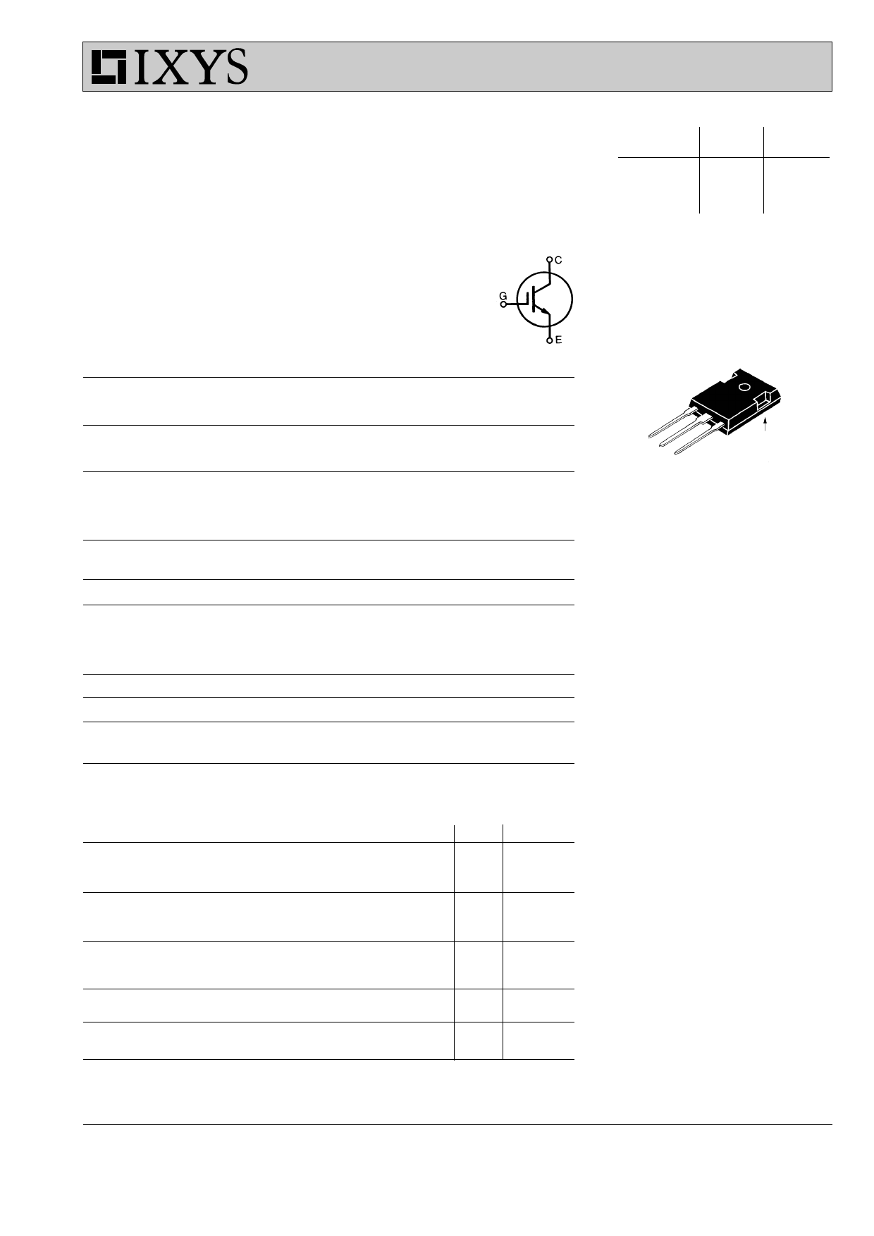
TO-247AD
G
CE
C (TAB)
G = Gate
E = Emitter
C = Collector
TAB = Collector
Features
• International standard package
JEDEC TO-247 AD
• 2nd generation HDMOSTM process
• Low VCE(sat)
- for low on-state conduction losses
• High current handling capability
• MOS Gate turn-on
- drive simplicity
• Voltage rating guaranteed at high
temperature (125°C)
Applications
• AC motor speed control
• DC servo and robot drives
• DC choppers
• Uninterruptible power supplies (UPS)
• Switch-mode and resonant-mode
power supplies
Advantages
• Easy to mount with 1 screw
(isolated mounting screw hole)
• High power density
IXYS reserves the right to change limits, test conditions, and dimensions.
© 2000 IXYS All rights reserved
95590B(7/00)
1-2
Share Link: 