RC1005 View Datasheet(PDF) - Samsung
Part Name
Description
Manufacturer
RC1005 Datasheet PDF : 2 Pages
| |||
Specification
Power Working Overload
Resistance Range (Ω)
Rated
Rated
Type Rating Voltage Voltage TCR (ppm/℃) G(±2%) J(±5%) K(±10%) Ambient Working
(W) (MAX) (MAX)
E-48
E-24
E-12 Temperature Temperature
RC0603 1/20 25(V)
50(V)
1Ω≤R〈10Ω
RC1005 1/16 50(V)
100(V) +300/-200ppm
RC1608 1/10
10Ω≤R≤1MΩ
RC2012 1/8
RC3216 1/4
150(V)
300(V)
±100ppm
(0603:±250ppm)
1Ω~1MΩ 1Ω~10MΩ
1Ω~10MΩ
70℃
-55℃~+125℃
-55℃~+155℃
RC3225 1/3
RC5025 2/3
RC6432 1
200(V)
400(V) 1MΩ〈R≤10MΩ
±300ppm
-55℃~+125℃
√ •Rated voltage (V) = Rated power(W)×Normal resistance value (R)
Rated voltage should be lower than (MAX) working voltage.
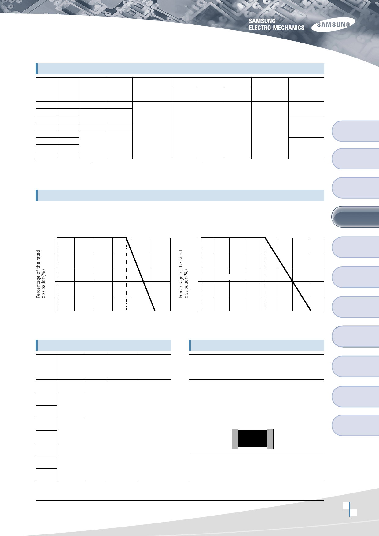
Power Derating Curve
The rated power is the maximum continuous loading power at 70℃ ambient temperature.
For ambient temperature above 70℃, the loading power follows the below power derating curve.
(The load current shall be derated according to derating curve in case of the 'Jumper')
<0603, 1005, 3225, 5025, 6432>
100
<1608, 2012, 3216>
100
80
60
Operation area
40
80
60
Operation area
40
20
-55
0
-40
0
70
125
40
80
120
Ambient Temperature(℃)
20
-55
0
-30 0
70
155
30 60 90 120 150
Ambient Temperature(℃)
Jumper Resistors
Type
Resistance
Current
Rating
Rated
Ambient
Temperature
Rated
Working
Temperature
RC 0603
RC 1005
RC 1608
RC 2012
RC 3216
RC 3225
RC 5025
RC 6432
50mΩ
Max.
0.5(A)
1.0(A)
2.0(A)
70℃ -55℃~+125℃
Marking
3 digits indication
(E-24 series)
- Left 2 digits represent significant figures.
- Last 1 digit represent exponential number of 10.
- Example: 103
Left 2 digits: 10
Last 1 digit: 3
103 = 10×103Ω
= 10000Ω=10kΩ
103
•Jumper chip is printed as 000
•Resistance below 10Ω is expressed using“R”
ex) 7R5=7.5Ω
•0603, 1005 type: No marking.
Operation
Notes
Example of Land
Pattern Design
Recommended
Soldering Conditions
General
Purpose
Precision
Low Ohms
Array
Attenuator
Characteristics
Performance
Packaging
Standard
Resistance Value
Design and Specifications are subject to change without prior notice.
8
Please ask the manufacturer for technical Specifications before you order and/or use.
9
Share Link: 