AP1014AEC View Datasheet(PDF) - Asahi Kasei Microdevices
Part Name
Description
Manufacturer
AP1014AEC Datasheet PDF : 13 Pages
| |||
[AP1014AEC]
Parameter
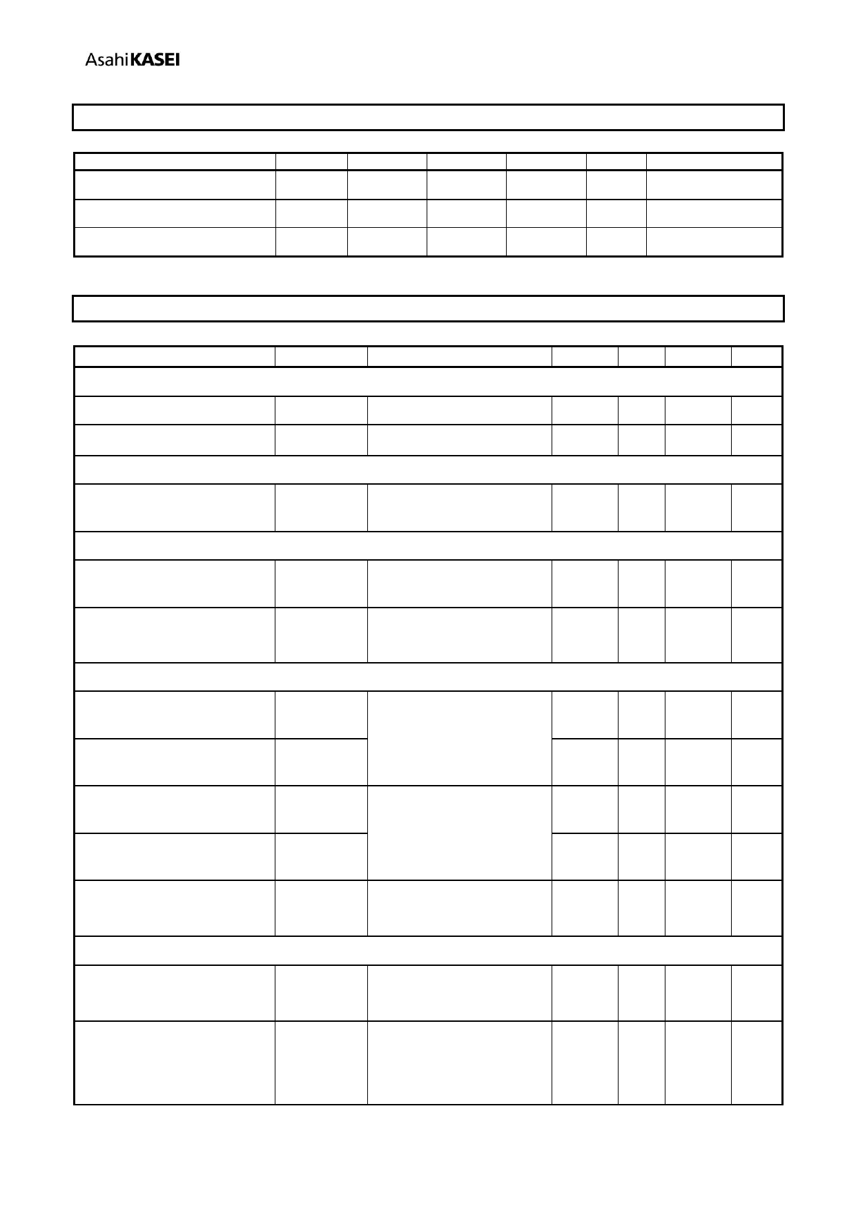
7. Recommended Operating Conditions
(Ta = 25℃, unless otherwise specified)
Symbol Min.
Typ.
Max. Unit Condition
Control supply voltage
VC
2.7
3.0
5.5
V
Motor driver supply voltage
VM
2.0
5.0
7.0
V
Input pulse frequency
Fin
-
-
200
kHz 50%duty
Parameter
Charge pump
Charge pump voltage
Charge pump wake up time
VDET
VC under voltage detect
voltage
TSD
Thermal shut down
temperature (Note 4)
Temperature hysteresis
(Note 4)
Quiescent current
VM quiescent current at
power off
VC quiescent current at
power off
VM quiescent current at
standby
VC quiescent current at
standby
VC quiescent current at
PWM operation
Motor Driver
Driver on resistance
(High side + Low side)
Driver on resistance
(High side + Low side)
(Note 4)
8. Electrical Characteristics
(Ta = 25℃, VM=5.0V, VC = 3.0V, unless otherwise specified)
Symbol
Condition
Min. Typ. Max. Unit
VG
tVGON
VG=VC+VM
VG=VC+VM-1.0V
7.0 7.5 8.0
V
‐ 0.3 3.0 ms
VCDETLV
1.9 2.2 2.5
V
TDET
TDETHYS
150 175 200 ℃
20
30
40
℃
IVMPOFF EN=”L”
-
All internal circuits are
IVCPOFF power off.
-
IVMSTBY EN=”H”, SEL=”L”
-
INnA=”L”, INnB=”L”
IVCSTBY
-
fPWM=200kHz,
IVCPWM
-
Duty=50%
-
1.0 μA
-
1.0 μA
40 200 μA
150 500 μA
0.5 1.5 mA
RON1
Iload=100mA, Ta=25℃
RON2
Design
certification
Iload=0.7A, Ta=25℃
- 0.35 0.46 Ω
- 0.38 0.53 Ω
MS1548-E-00
-7-
2014/03
Share Link: 