FM24CL64B-DGTR View Datasheet(PDF) - Cypress Semiconductor
Part Name
Description
Manufacturer
FM24CL64B-DGTR Datasheet PDF : 18 Pages
| |||
FM24CL64B
AC Switching Characteristics
Over the Operating Range
Parameter [6]
Cypress
Alt.
Parameter Parameter
Description
fSCL[7]
SCL clock frequency
tSU; STA
Start condition setup for repeated Start
tHD;STA
Start condition hold time
tLOW
Clock LOW period
tHIGH
Clock HIGH period
tSU;DAT
tSU;DATA Data in setup
tHD;DAT
tHD;DATA Data in hold
tDH
tR[8]
tr
tF[8]
tf
Data output hold (from SCL @ VIL)
Input rise time
Input fall time
tSU;STO
STOP condition setup
tAA
tVD;DATA SCL LOW to SDA Data Out Valid
tBUF
Bus free before new transmission
tSP
Noise suppression time constant on SCL, SDA
Min Max Min Max Min Max Unit
– 0.1 – 0.4 – 1.0 MHz
4.7 – 0.6 – 0.25 – s
4.0 – 0.6 – 0.25 – s
4.7 – 1.3 – 0.6 – s
4.0 – 0.6 – 0.4 – s
250 – 100 – 100 – ns
0
–
0
–
0
– ns
0
–
0
–
0
– ns
– 1000 – 300 – 300 ns
– 300 – 300 – 100 ns
4.0 – 0.6 – 0.25 – s
–
3
– 0.9 – 0.55 s
4.7 – 1.3 – 0.5 – s
– 50 – 50 – 50 ns
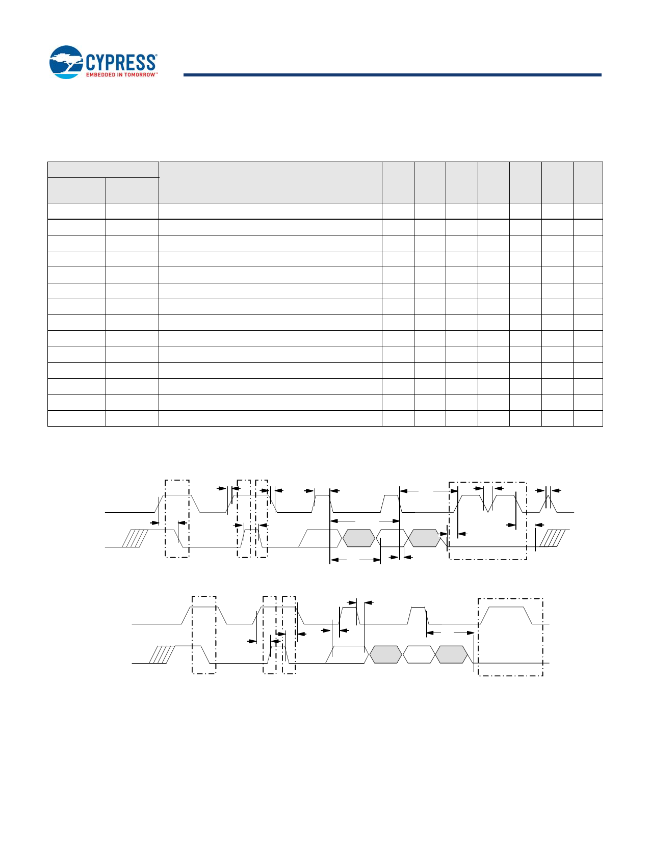
Figure 14. Read Bus Timing Diagram
tR
` tF
tHIGH
tLOW
tSP
tSP
SCL
tSU:SDA
tBUF
SDA
1/fSCL
tHD:DAT
tSU:DAT
Start
Stop Start
tAA
tDH
Acknowledge
Figure 15. Write Bus Timing Diagram
SCL
SDA
tSU:STO
tHD:DAT
tHD:STA
tSU:DAT
tAA
Start
Stop Start
Acknowledge
Notes
6. Test conditions assume signal transition time of 10 ns or less, timing reference levels of VDD/2, input pulse levels of 0 to VDD(typ), and output loading of the specified
IOL and load capacitance shown in Figure 13.
7. The speed-related specifications are guaranteed characteristic points along a continuous curve of operation from DC to fSCL (max).
8. These parameters are guaranteed by design and are not tested.
Document Number: 001-84458 Rev. *I
Page 11 of 18
Share Link: 