LH168A View Datasheet(PDF) - Sharp Electronics
Part Name
Description
Manufacturer
LH168A Datasheet PDF : 14 Pages
| |||
LH168A
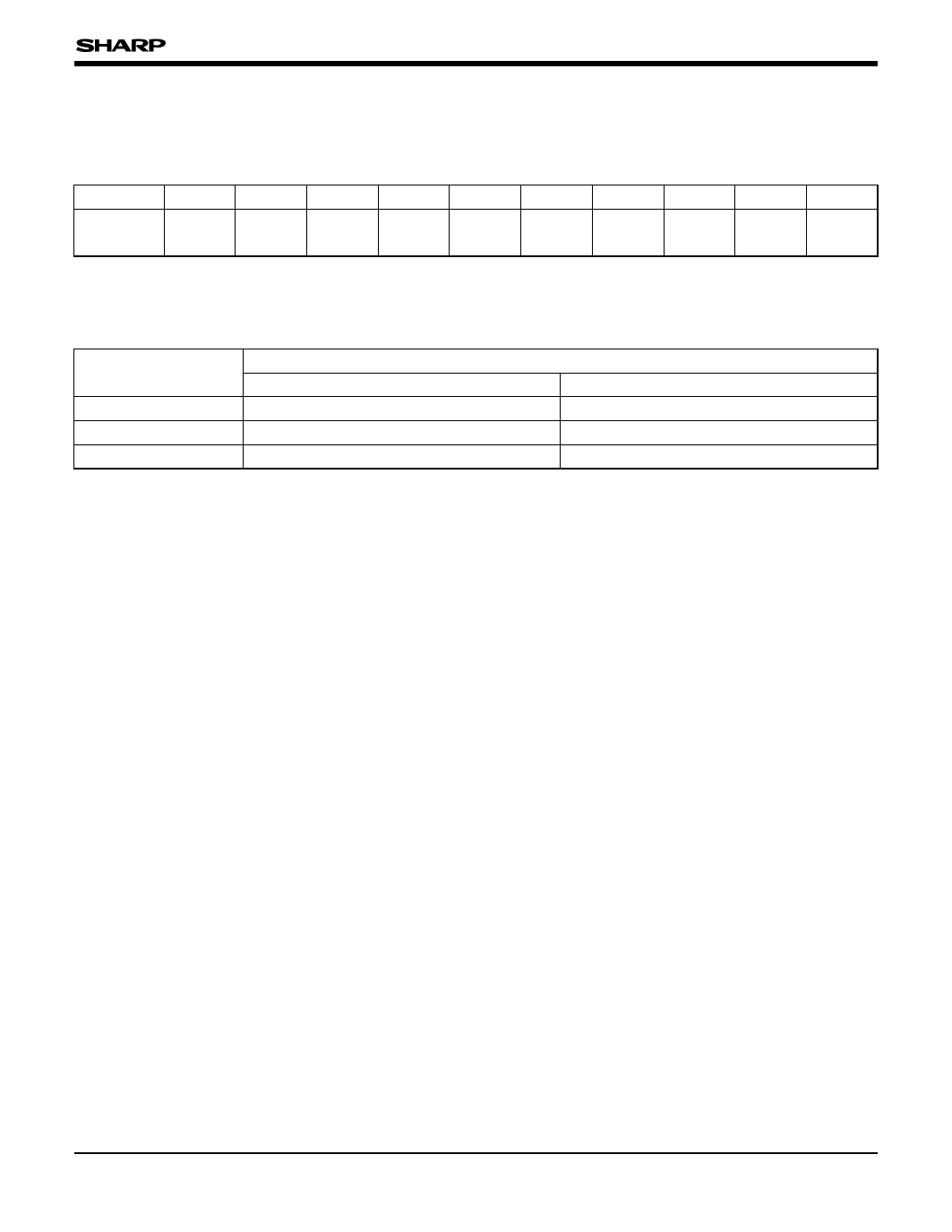
Functional Operations
The following describes the relation between data
input pin and output direction.
Data input pin XA0-XA5 YA0-YA5 ZA0-ZA5 XB0-XB5 YB0-YB5 ZB0-ZB5
Output
XO1
YO1
ZO1
XO2
YO2
ZO2
direction
πππ
πππ
XB0-XB5 YB0-YB5 ZB0-ZB5
XO128 YO128 ZO128
The following describes the relation between LBR
pin, SPOI pin, SPIO pin and output direction.
PIN
LBR
OUTPUT DIRECTION
RIGHT SHIFT (XO1, YO1, ZO1/XO128, YO128, ZO128) LEFT SHIFT (ZO128, YO128, XO128/ZO1, YO1, XO1)
H
L
SPOI
Input
Output
SPIO
Output
Input
NOTE :
Color data corresponding to X, Y, and Z vary depending on the output direction.
7
Share Link: 