MIC2524 View Datasheet(PDF) - Micrel
Part Name
Description
Manufacturer
MIC2524 Datasheet PDF : 12 Pages
| |||
MIC2524/2527
Applications Information
Supply Filtering
A 0.1µF to 1µF bypass capacitor from IN to GND, located at
the device, is strongly recommended to control supply tran-
sients. Without a bypass capacitor, an output short may
cause sufficient ringing on the input (from supply lead induc-
tance) to damage internal control circuitry.
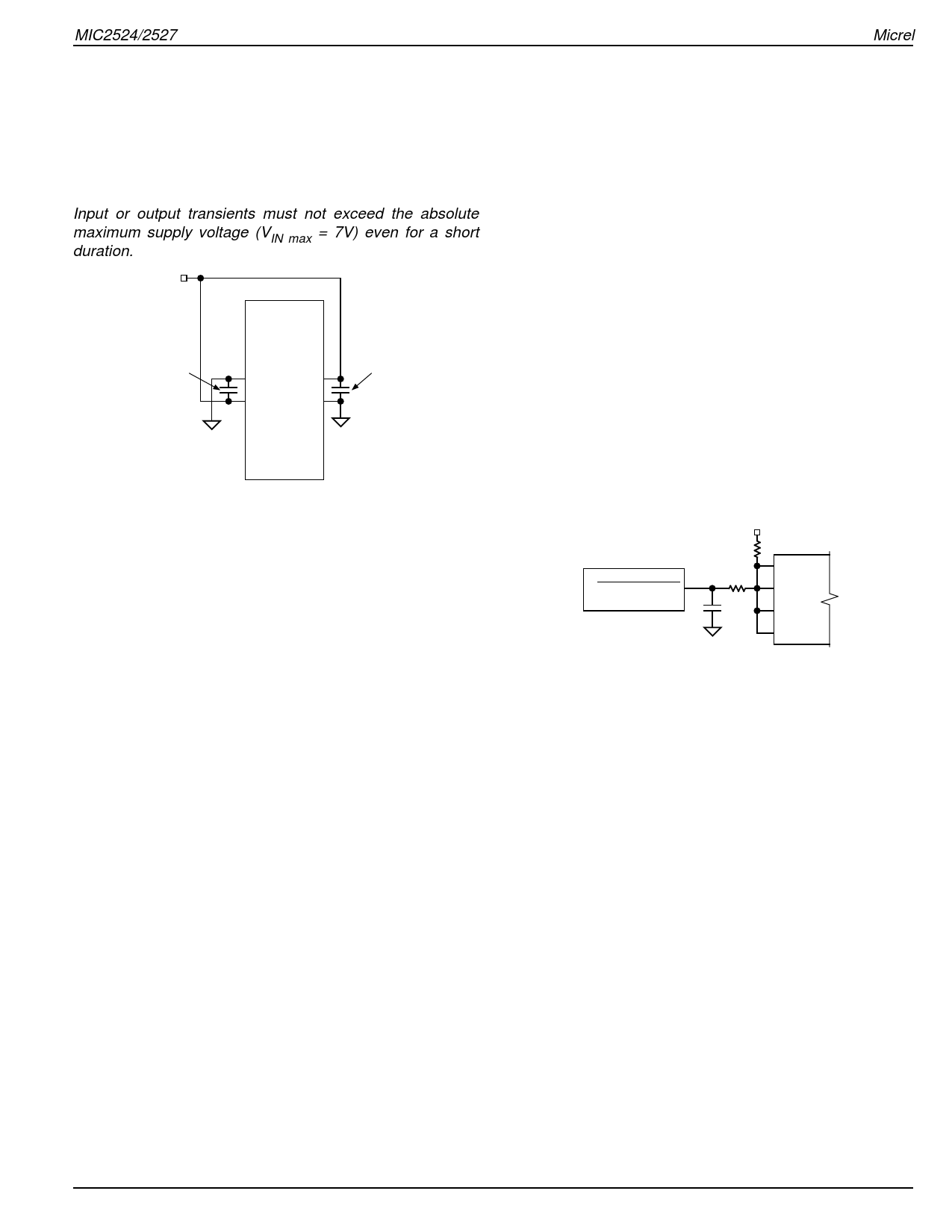
Input or output transients must not exceed the absolute
maximum supply voltage (VIN max = 7V) even for a short
duration.
VIN
2.7V to 5.5V
0.1µF to 1µF
MIC2524/7
FLGA FLGB
ENA ENB
OUTA OUTB
GND
IN
IN
GND
OUTC OUTD
ENC END
FLGC FLGD
0.1µF to 1µF
Figure 1. Supply Bypassing
Enable Input
EN must be driven logic high or logic low for a clearly defined
input. Floating the input may cause unpredictable operation.
EN should not be allowed to go negative with respect to GND.
Soft Start
The MIC2524/7 presents a high impedance when off, and
slowly becomes a low impedance as it turns on. This reduces
inrush current and related voltage drop that results from
charging a capacitive load, satisfying the USB voltage droop
requirements.
Micrel
Transient Overcurrent Filter
When the MIC2524/7 is enabled, large values of capacitance
at the output of the device will cause inrush current to exceed
the short circuit current-limit threshold of the device and
assert the flag. The duration of this time will depend on the
size of the output capacitance. Refer to the “Functional
Characteristics” turn-on and turnoff behaviors for details.
During the capacitance charging time, the device enters into
constant-current mode. As the capacitance is charged, the
current decreases below the short circuit current-limit thresh-
old, and the flag will then be deasserted.
In USB applications, it is required that output bulk capaci-
tance is utilized to support hot-plug events. When the
MIC2524/7 is enabled, the flag may go active for about 1ms
due to inrush current exceeding the current-limit setpoint.
Additionally, during hot-plug events, inrush currents may also
cause the flag to go active for 30µs. Since these conditions
are not valid overcurrent faults, the USB controller must
ignore the flag during these events. To prevent this erroneous
overcurrent reporting, a 1ms RC filter as shown in Figure 2
may be used. Alternatively, a 1ms debounce routine may be
programmed into the USB logic controller, eliminating the
need for the RC filter.
USB Controller
OVERCURRENT
10k
10k
0.1µF
FLGA
FLGB
FLGC
FLGD
Figure 2. Transient Filter
June 1999
9
MIC2524/2527
Share Link: 