MAX4548 View Datasheet(PDF) - Maxim Integrated
Part Name
Description
Manufacturer
MAX4548 Datasheet PDF : 20 Pages
| |||
Serially Controlled, Triple 3x2 Audio/Video
Crosspoint Switches
3-WIRE TIMING CHARACTERISTICS (Figure 5)
(V+ = +2.7V to +5.25V, TA = TMIN to TMAX, unless otherwise noted.)
PARAMETER
SYMBOL
CONDITIONS
Operating Frequency
V+ = 4.75V to 5.25V
fOP
V+ = 2.7V to 5.25V
DIN to SCLK Setup
tDS
DIN to SCLK Hold
tDH
SCLK Fall to Output Data Valid
CS to SCLK Rise Setup
CS to SCLK Rise Hold
CS Pulse Width High
tDO
tCSS
tCSH
tCSW
CLOAD = 50pF
SCLK Pulse Width High
tCH
SCLK Pulse Width Low
tCL
Rise Time (SCLK, DIN, CS)
tR
Fall Time (SCLK, DIN, CS)
tF
MIN TYP MAX UNITS
0
10
MHz
0
2.1
100
ns
0
ns
200
ns
100
ns
0
ns
40
ns
200
ns
200
ns
2
µs
2
µs
Note 2: The algebraic convention is used in this data sheet; the most negative value is shown in the minimum column.
Note 3: Guaranteed by design. Not subject to production testing.
Note 4: ∆RON = RON(MAX) - RON(MIN).
Note 5: Resistance flatness is defined as the difference between the maximum and minimum on-resistance values, as measured
over the specified analog signal range.
Note 6: Leakage parameters are 100% tested at maximum rated temperature and guaranteed by correlation at TA = +25°C.
Note 7: Off-isolation = 20log (VCOM_ / VNO_ _ ), VCOM_ = output, VNO_ _ = input to off switch.
Note 8: All timing is measured from the clock’s falling edge preceding the ACK signal for 2-wire and from the rising edge of CS for
3-wire. Turn-off time is defined at the output of the switch for a 0.5V change, tested with a 300Ω load to ground. Turn-on
time is defined at the output of the switch for a 0.5V change and measured with a 5kΩ load resistor to GND. All timing is
shown with respect to 20% V+ and 70% V+, unless otherwise noted.
Note 9: Supply current can be as high as 2mA per switch during switch transitions in the clickless mode, corresponding to a 48mA
total supply transient current requirement.
Note 10: Leakage testing is guaranteed by testing with a +5.25V supply.
Note 11: Cb = capacitance of one bus line in pF. Tested with Cb = 400pF.
Note 12: Typical values are for MAX4548 devices.
(V+ = +5V, TA = +25°C, unless otherwise noted.)
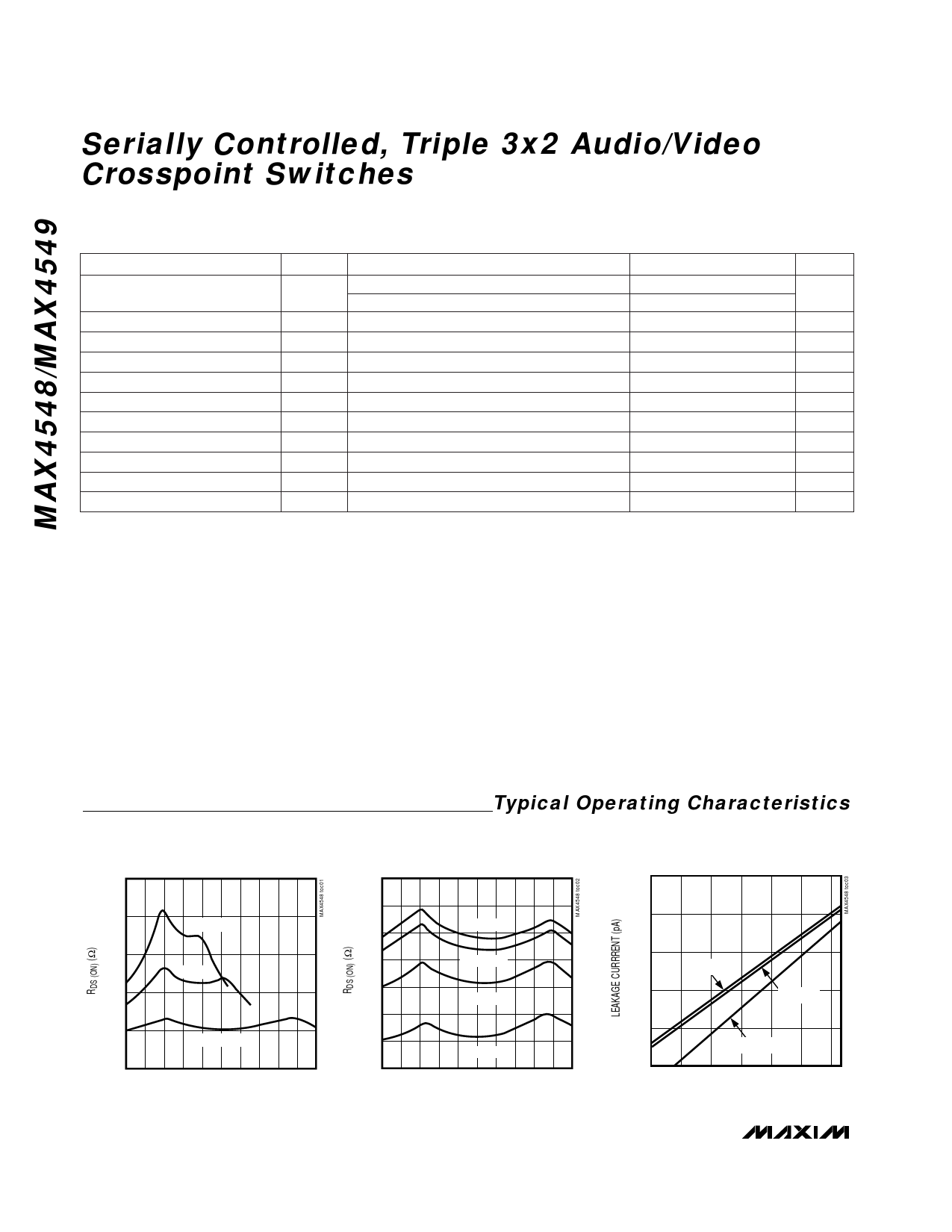
ON-RESISTANCE vs. VCOM
40
28
Typical Operating Characteristics
ON-RESISTANCE
vs. VCOM AND TEMPERATURE
LEAKAGE CURRENT vs. TEMPERATURE
10,000
35
V+ = 2.7V
30
V+ = 3.3V
25
20
V+ = 5.0V
15
0 0.5 1.0 1.5 2.0 2.5 3.0 3.5 4.0 4.5 5.0
VCOM (V)
26
TA = +85°C
24
22
TA = +70°C
20
TA = +25°C
18
16
14
0
TA = -40°C
0.5 1.0 1.5 2.0 2.5 3.0 3.5 4.0 4.5 5.0
VCOM (V)
1000
100
COM_ON
10
COM_OFF
1
NO_OFF
0.1
-40 -20 0
20 40 60 80
TEMPERATURE (°C)
6 _______________________________________________________________________________________
Share Link: 