MBR0540T1G View Datasheet(PDF) - ON Semiconductor
Part Name
Description
Manufacturer
MBR0540T1G Datasheet PDF : 6 Pages
| |||
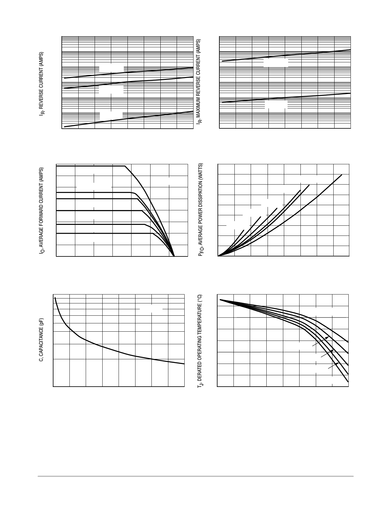
MBR0540T1G, NRVB0540T1G, MBR0540T3G, NRVB0540T3G
100E-3
100E-3
10E-3
1.0E-3
TJ = 125C
10E-3
1.0E-3
TJ = 100C
100E-6
10E-6
1.0E-6
100E-9
0
TJ = 100C
TJ = 25C
10
20
30
VR, REVERSE VOLTAGE (VOLTS)
Figure 3. Typical Reverse Current
100E-6
10E-6
1.0E-6
100E-9
40
0
TJ = 25C
10
20
30
40
VR, REVERSE VOLTAGE (VOLTS)
Figure 4. Maximum Reverse Current
0.8
dc
0.7
0.6
SQUARE WAVE
0.5
Ipk/Io = p
0.4
Ipk/Io = 5
0.3
Ipk/Io = 10
0.2
Ipk/Io = 20
0.1
FREQ = 20 kHz
0.45
0.40
SQUARE WAVE
dc
0.35
Ipk/Io = p
0.30
0.25
Ipk/Io = 5
0.20
Ipk/Io = 10
0.15
Ipk/Io = 20
0.10
0.05
0
0
20
40
60
80
100 120 140
0
0 0.1 0.2 0.3 0.4 0.5 0.6 0.7 0.8
TL, LEAD TEMPERATURE (C)
Figure 5. Current Derating
IO, AVERAGE FORWARD CURRENT (AMPS)
Figure 6. Forward Power Dissipation
100
126
TJ = 25C
124
122
Rtja = 118C/W
120
10
0 5.0 10 15 20 25 30 35 40
VR, REVERSE VOLTAGE (VOLTS)
Figure 7. Capacitance
118
149C/W
116
180C/W
114
206C/W
112
228C/W
110
0 5.0 10 15 20 25 30 35 40
VR, DC REVERSE VOLTAGE (VOLTS)
Figure 8. Typical Operating Temperature Derating*
* Reverse power dissipation and the possibility of thermal runaway must be considered when operating this device under any
reverse voltage conditions. Calculations of TJ therefore must include forward and reverse power effects. The allowable operating
TJ may be calculated from the equation:
TJ = TJmax − r(t)(Pf + Pr) where
r(t) = thermal impedance under given conditions,
Pf = forward power dissipation, and
Pr = reverse power dissipation
This graph displays the derated allowable TJ due to reverse bias under DC conditions only and is calculated as
TJ = TJmax − r(t)Pr, where r(t) = Rthja. For other power applications further calculations must be performed.
http://onsemi.com
3
Share Link: 