EL8102(2004) View Datasheet(PDF) - Intersil
Part Name
Description
Manufacturer
EL8102 Datasheet PDF : 12 Pages
| |||
EL8102, EL8103
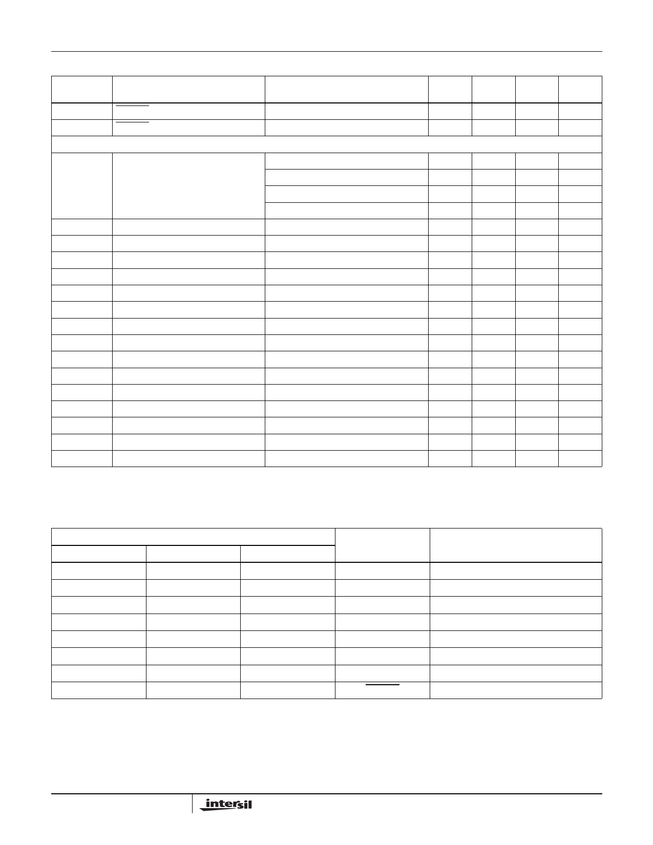
Electrical Specifications VS+ = 5V, VS- = GND, TA = 25°C, VCM = 2.5V, RL to 2.5V, AV = 1, Unless Otherwise Specified (Continued)
PARAMETER
DESCRIPTION
CONDITIONS
MIN
TYP
MAX
UNIT
AC PERFORMANCE
BW
-3dB Bandwidth
BW
Peak
GBWP
±0.1dB Bandwidth
Peaking
Gain Bandwidth Product
AV = +1, RF = 0Ω, CL = 5pF
AV = -1, RF = 1kΩ, CL = 5pF
AV = +2, RF = 1kΩ, CL = 5pF
AV = +10, RF = 1kΩ, CL = 5pF
AV = +1, RF = 0Ω, CL = 5pF
AV = +1, RL = 1kΩ, CL = 5pF
500
MHz
140
MHz
165
MHz
18
MHz
35
MHz
1
dB
200
MHz
PM
Phase Margin
SR
Slew Rate
tR
Rise Time
tF
Fall Time
OS
Overshoot
RL = 1kΩ, CL = 5pF
55
AV = 2, RL = 100Ω, VOUT = 0.5V to 4.5V
500
600
2.5VSTEP, 20% - 80%
4
2.5VSTEP, 20% - 80%
2
200mV step
10
°
V/µs
ns
ns
%
tPD
Propagation Delay
200mV step
tS
0.1% Settling Time
200mV step
dG
Differential Gain
AV = +2, RF = 1kΩ, RL = 150Ω
dP
Differential Phase
AV = +2, RF = 1kΩ, RL = 150Ω
eN
Input Noise Voltage
f = 10kHz
iN+
Positive Input Noise Current
f = 10kHz
iN-
Negative Input Noise Current
f = 10kHz
1
ns
15
ns
0.01
%
0.01
°
12
nV/√Hz
1.7
pA/√Hz
1.3
pA/√Hz
Pin Descriptions
EL8102IS
1
2
3
4
5
6
7
8
PIN
EL8102IW
4
3
2
1
6
5
EL8103IW
4
3
2
1
5
NAME
NC
IN-
IN+
VS-
NC
OUT
VS+
ENABLE
FUNCTION
Not connected
Inverting input
Non-inverting input
Negative power supply
Not connected
Amplifier output
Positive power supply
Enable and disable input
3
Share Link: 