MSA180 View Datasheet(PDF) - Oki Electric Industry
Part Name
Description
Manufacturer
MSA180 Datasheet PDF : 17 Pages
| |||
¡ Semiconductor
MSA180
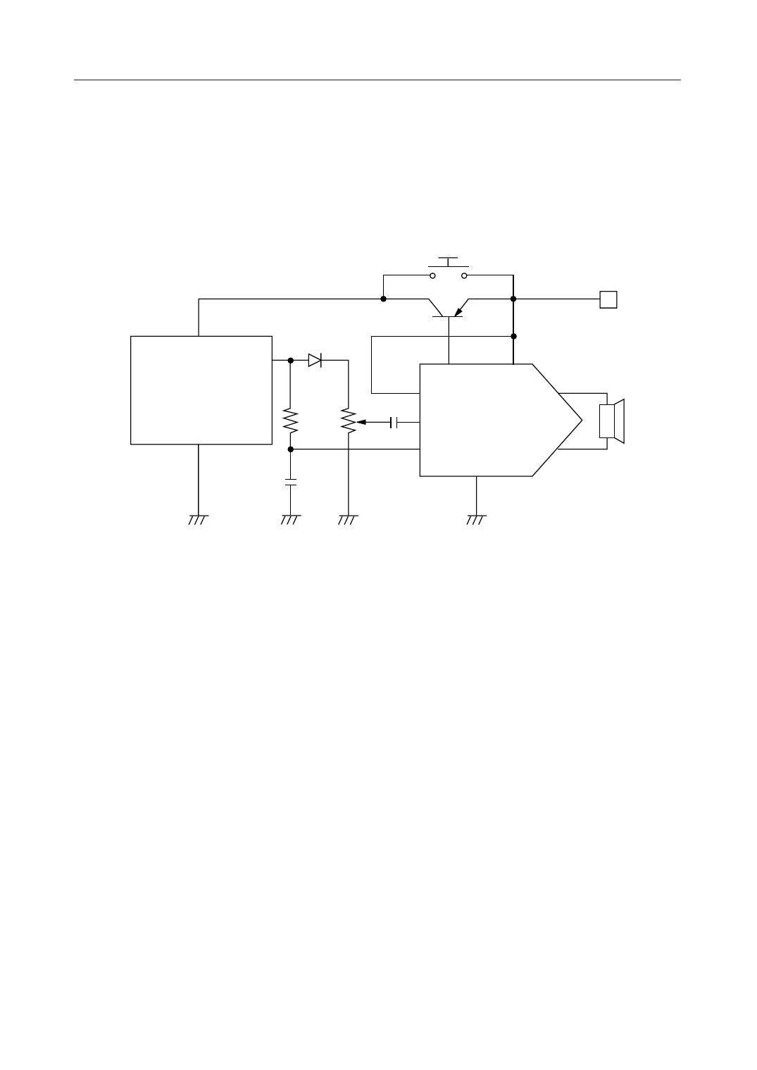
Application Example for Circuits Containing the MSM6378A/MSM6379 Speech Synthesizers
This example shows how to connect the MSA180 with an MSM6378A or MSM6379 speech
synthesizer using an external transistor and the MODE1 pin. The analog output of both synthesizers
lowers to 0 V in their standby mode. For this reason, the voice signal can be used to control operation
and standby modes of the MSA180. The circuit also controls the voltage via an external transistor.
If this function is not used, leave the BASE pin open.
START SWITCH
VDD
VDD
AOUT
MSM6378A
or MSM6379
R2
R1
BASE
MODE2
VCC
PIEZO SPEAKER
SP
C1 AIN MSA180
GND
MODE1
SP
C2
GND
Operation Flow
1. When the start switch is pressed, power is supplied to the VDD pins on the MSM6378A or
MSM6379, and operation mode is invoked. Voice output level then rises.
2. When operation mode is involved, the voice signal rises above the GND level, and MODE1 on
MSA180 goes high (H).
3. The BASE pin on MSA180 goes low (L) to drive the external transistor for power-supply control.
4. The audio IC continues to operate using the external transistor as a power supply. The device
continues to operate and voice sounds, even if the start switch is released at this time.
5. When the sound ends, MODE1 on MSA180 falls low (L), the voice signal falls to GND level, and
standby mode ensues.
6. The external transistor for power-supply control is switched off, switching the voice synthesizer
off because the power supply is switched off.
7/16
Share Link: 