74VHC139T View Datasheet(PDF) - STMicroelectronics
Part Name
Description
Manufacturer
74VHC139T Datasheet PDF : 8 Pages
| |||
74VHC139
AC ELECTRICAL CHARACTERISTICS (Input tr = tf =3 ns)
Symb ol
Parameter
tPLH Propagation Delay
tPHL Time
A, B, to Y
tPLH Propagation Delay
tPHL Time
G to Y
(*) Voltage range is 3.3V ± 0.3V
(**) Voltage range is 5V ± 0.5V
Test Condition
V CC
CL
( V)
(pF)
3.3(*)
15
3.3(*)
50
5.0(**)
15
5.0(**)
50
3.3(*)
15
3.3(*)
50
5.0(**)
15
5.0(**)
50
Value
TA = 25 oC
Min. Typ. Max.
7.2 11.0
9.7 14.5
5.0 7.2
6.5 9.2
6.4 9.2
8.9 12.7
4.4 6.3
5.9 8.3
-40 to 85 oC
Min . Max.
1.0 13.0
1.0 16.5
1.0 8.5
1.0 10.5
1.0 11.0
1.0 14.5
1.0 7.5
1.0 9.5
Unit
ns
ns
CAPACITIVE CHARACTERISTICS
Symb ol
Parameter
Test Conditions
Value
Un it
TA = 25 oC
-40 to 85 oC
Min. Typ . Max. Min . Max.
CIN Input Capacitance
4
10
10
pF
CPD Power Dissipation
Capacitance (note 1)
26
pF
1) CPD isdefined as the value of the IC’sinternal equivalent capacitance which is calculated fromthe operating current consumption without load. (Referto
Test Circuit).Average operating current can be obtained by the following equation. ICC(opr) = CPD • VCC • fIN + ICC/2 (per Decoder)
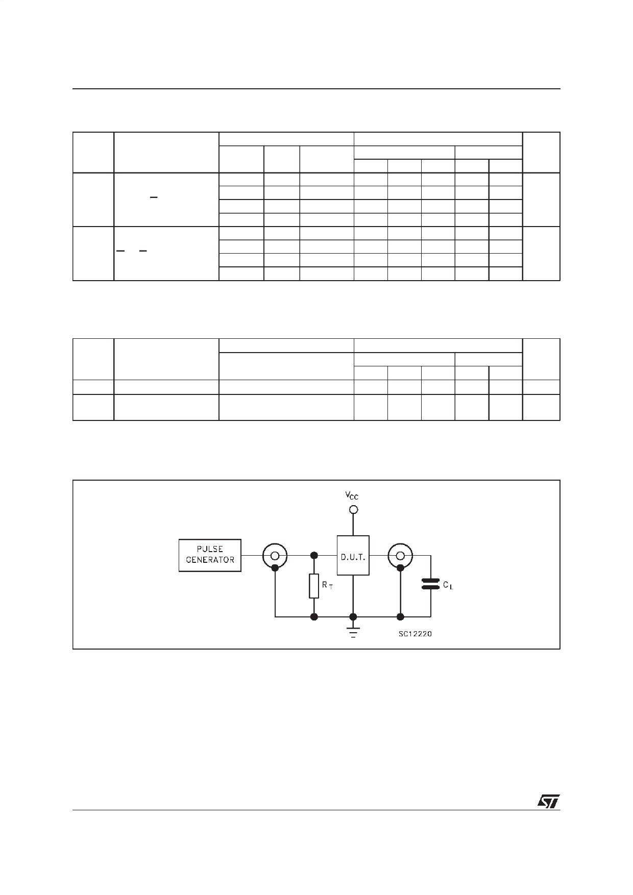
TEST CIRCUIT
CL = 15/50 pF or equivalent (includes jig and probe capacitance)
RT = ZOUT of pulse generator (typically 50Ω)
4/8
Share Link: 