AD1864 View Datasheet(PDF) - Analog Devices
Part Name
Description
Manufacturer
AD1864 Datasheet PDF : 12 Pages
| |||
AD1864
SM5813AP/A
1
PT
28
2
27
3
BCKO 26
4
WCKO 25
5
DOL 24
6
DOR 23
7
8 VSS1
9
VDD 22
VSS2 21
DG 20
10
19
11
18
12
OW18 17
13
OW20 16
14
15
–5V ANALOG SUPPLY
+5V ANALOG SUPPLY
AD1864
1 –VS
+VS 24
2 TRIM TRIM 23
3 MSB
MSB 22
C1
C2
4 I OUT
IOUT 21
5 AGND AGND 20
6 SJ
SJ 19
7 RF
8 VOUT
R F 18
VOUT 17
9 +V L
10 DR
–VL 16
DL 15
11 LR
LL 14
12 CLK DGND 13
1
+VS 8
2
7
3
6
4 –VS
5
AD712
OR
NE5532
LEFT
CHANNEL
OUTPUT
RIGHT
CHANNEL
OUTPUT
+5V DIGITAL SUPPLY
–5V DIGITAL SUPPLY
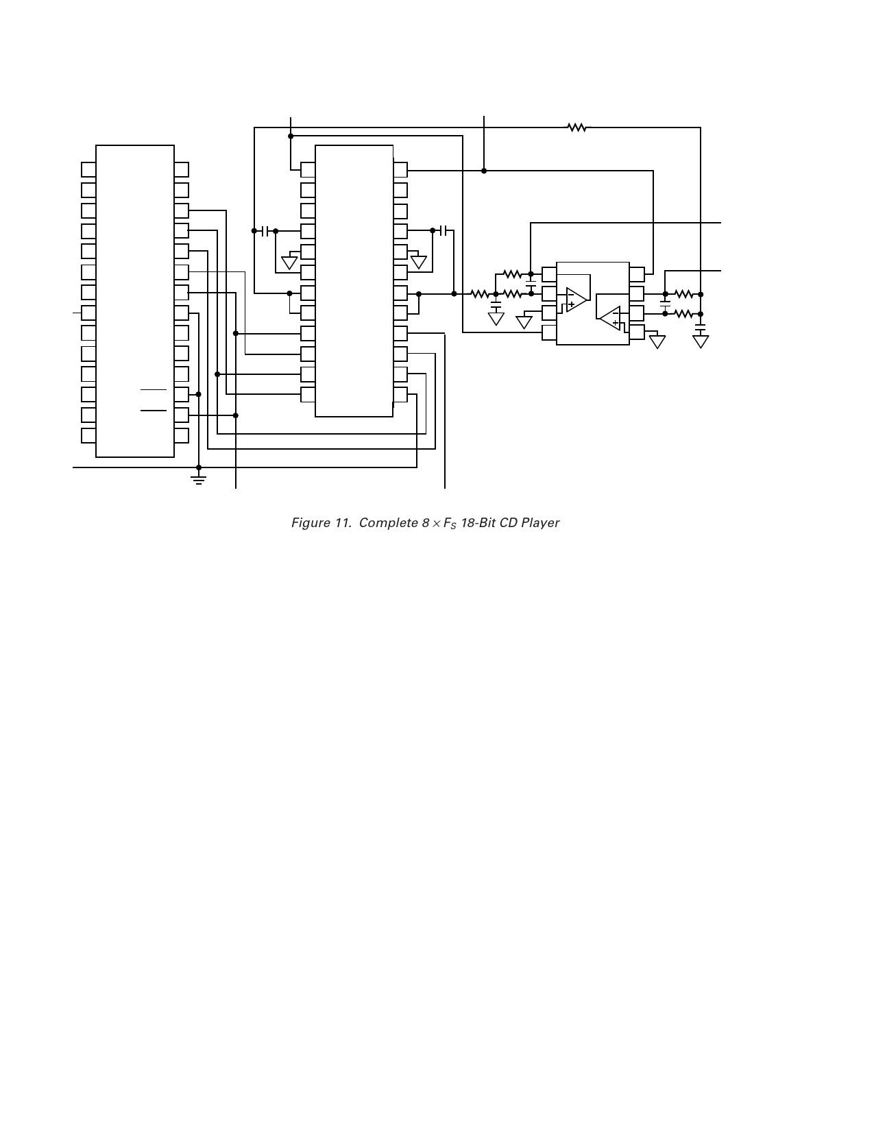
Figure 11. Complete 8 × FS 18-Bit CD Player
8-BIT CD PLAYER DESIGN
Figure 11 illustrates an 18-bit CD player design incorporating
an AD1864 D/A converter, an AD712 or NE5532 dual op amp
and the SM5813 digital filter chip manufactured by NPC. In
this design, the SM5813 filter transmits left and right digital
data to both channels of the AD1864. The left and right latch
signals, LL and LR, are both provided by the word clock signal
(WCKO) of the digital filter. The digital filter supplies data at
an 8 × FS oversample rate to each channel.
The digital data is converted to analog output voltages by the
output amplifiers on the AD1864. Note that no external
components are required by the AD1864. Also, no deglitching
circuitry is required.
An AD712 or NE5532 dual op amp is used to provide the
output antialias filters required for adequate image rejection.
One 2-pole filter section is provided for each channel. An
additional pole is created from the combination of the internal
feedback resistors (RF) and the external capacitors C1 and C2.
For example, the nominal 3 kΩ RF with a 360 pF capacitor for
C1 and C2 will place a pole at approximately 147 kHz, effec-
tively eliminating all high frequency noise components.
Close matching of the ac characteristics of the amplifiers on the
AD712 as well as their low distortion make it an ideal choice for
the task.
LOW distortion, superior channel separation, low power
consumption and a low component count are all realized by this
simple design.
–8–
REV. A
Share Link: 