L702 View Datasheet(PDF) - STMicroelectronics
Part Name
Description
Manufacturer
L702 Datasheet PDF : 7 Pages
| |||
THERMAL DATA
Symbol
Rth j-amb
Rth j-pins 9/16
Rth j-case
Parameter
Thermal Resistance Junction Ambient
}
Thermal Resistance Junction Pins 9 to 16
Thermal Resistance Junction-case
Powerdip
Multiwatt
Max
Max
Max
Value
70
14
3
L702
Unit
°C/W
°C/W
°C/W
ELECTRICAL CHARACTERISTICS (Tcase = 25°C unless otherwise specified)
Symbol
Parameter
Test conditions
Min. Typ. Max. Unit
ICEX Output Leakage Current
VCE = 90 V
10
50
µA
VCE(sust) Collector Emitter (°) Sustaining IC = 100 mA
Voltage
70
V
VCE(sat) Collector Emitter Saturation
Voltage
IC = 1.25 A
Ii = 2 mA
1.3
1.9
V
hFE DC Forward Current Gain
IC = 1 A
VCE = 3 V
1.000 4.000
Ii
Input Current
Vi = 3.75 V
Vi = 2.4 V
Open Collector
7
11
mA
3
6
mA
Vi
Input Voltage Off Condition VCE = 70 V
IC ≤ 0.1 mA
0.4
V
On Condition VCE = 3 V
IC ≥ 1 A
2.4
V
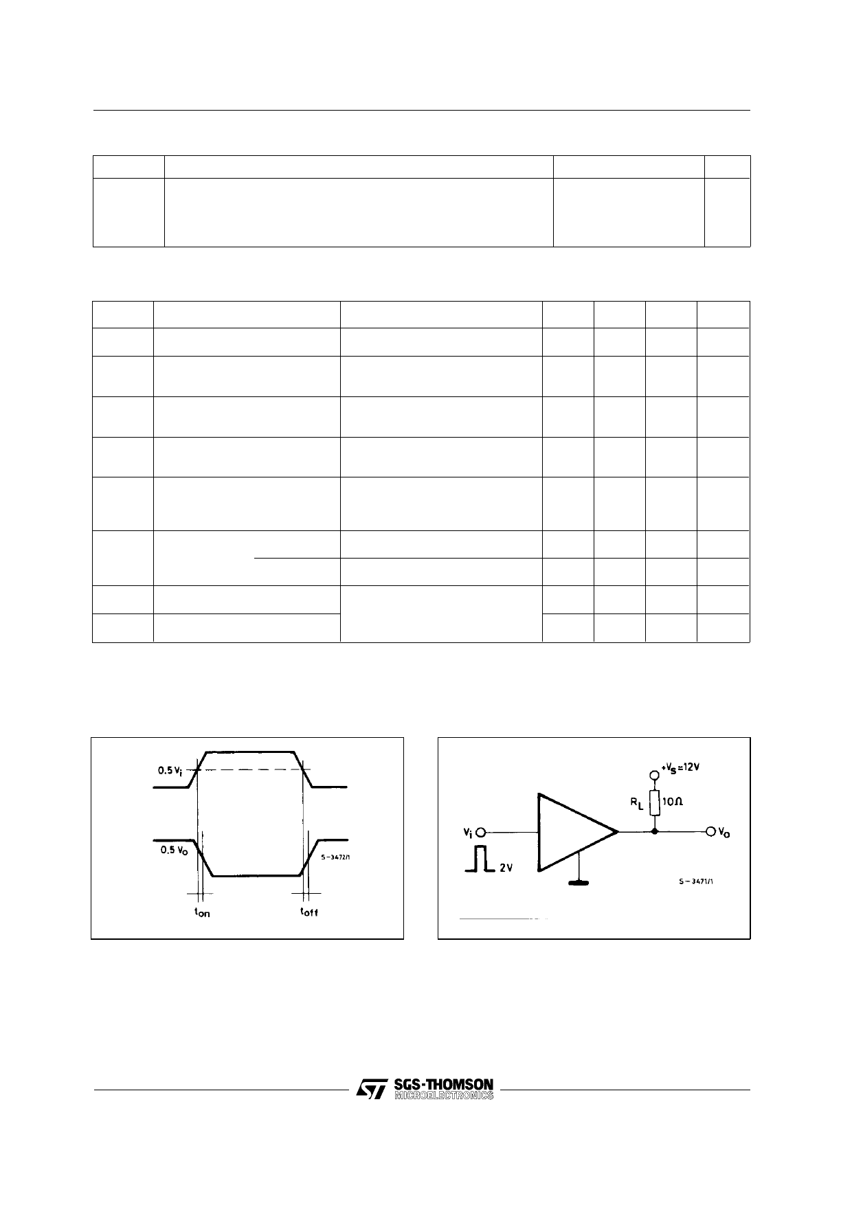
Ton Turn On Time
Vs = 12 V
0.3
µs
Toff Turn Off Time
RL = 10 Ω
1
µs
Figure 1. Switching Time.
Figure 2. ton and toff Test Circuit.
3/7
Share Link: 