B82796C2474N215 View Datasheet(PDF) - EPCOS AG
Part Name
Description
Manufacturer
B82796C2474N215 Datasheet PDF : 7 Pages
| |||
Data and signal line chokes
Common-mode chokes, ring core
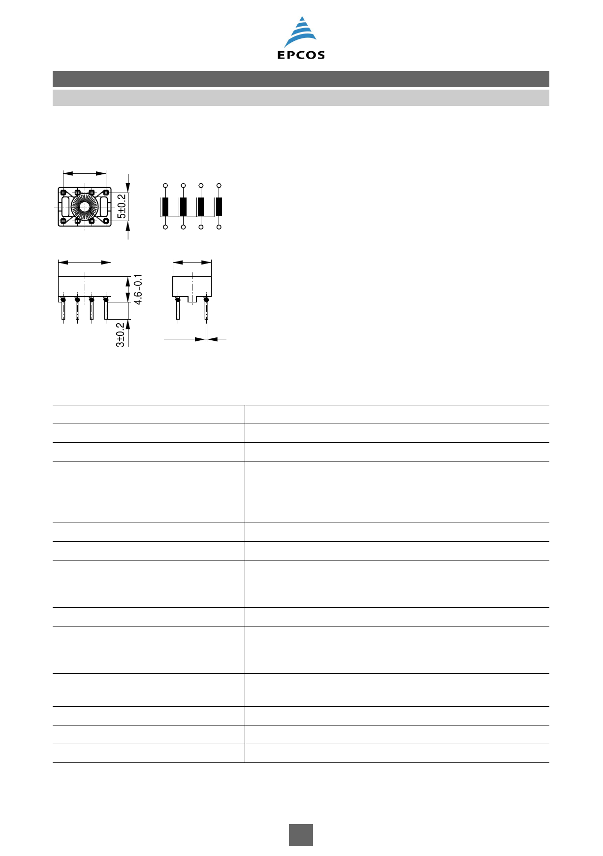
Dimensional drawing and pin configuration
3 x 2.5±0.2
1 23 4
1234
B82796C2
8765
9.2±0.1
8765
6.7±0.1
0.5 x 0.5
IND0217-H
Tolerances to ISO 2768-M
unless otherwise noted.
Dimensions in mm
Technical data and measuring conditions
Rated voltage VR
Rated temperature TR
Rated current IR
Rated inductance LR
Inductance tolerance
Inductance decrease ΔL/L0
Stray inductance Lstray,typ
DC resistance Rtyp
Solderability (lead-free)
Resistance to soldering heat
(wave soldering)
Climatic category
Storage conditions (packaged)
Weight
42 V AC (50/60 Hz) / 80 V DC
60 °C
Referred to 50 Hz and rated temperature
Measured with Agilent 4284A at 0.1 mA, 20 °C
Measuring frequency: LR ≤ 1 mH = 100 kHz
LR > 1 mH = 10 kHz
Inductance is specified per winding.
–30%/+50% at 20 °C
< 10% at DC magnetic bias with IR, 20 °C
Measured with Agilent 4284A at 5 mA, 20 °C, typical values
Measuring frequency: LR ≤ 11 μH = 100 kHz
LR > 11 μH = 10 kHz
Measured at 20 °C, typical values, specified per winding
Sn96.5Ag3.0Cu0.5: (245 ±5) °C, (3 ±0.3) s
Wetting of soldering area ≥ 95%
(to IEC 60068-2-20, test Ta)
(260 ±5) °C, (10 ±1) s
(to IEC 60068-2-20, test Tb)
40/125/56 (to IEC 60068-1)
–25 °C … +40 °C, ≤ 75% RH
Approx. 0.4 g
Please read Cautions and warnings and
Important notes at the end of this document.
3 10/08
Share Link: 