IDT54FCT138ATE View Datasheet(PDF) - Integrated Device Technology
Part Name
Description
Manufacturer
IDT54FCT138ATE Datasheet PDF : 6 Pages
| |||
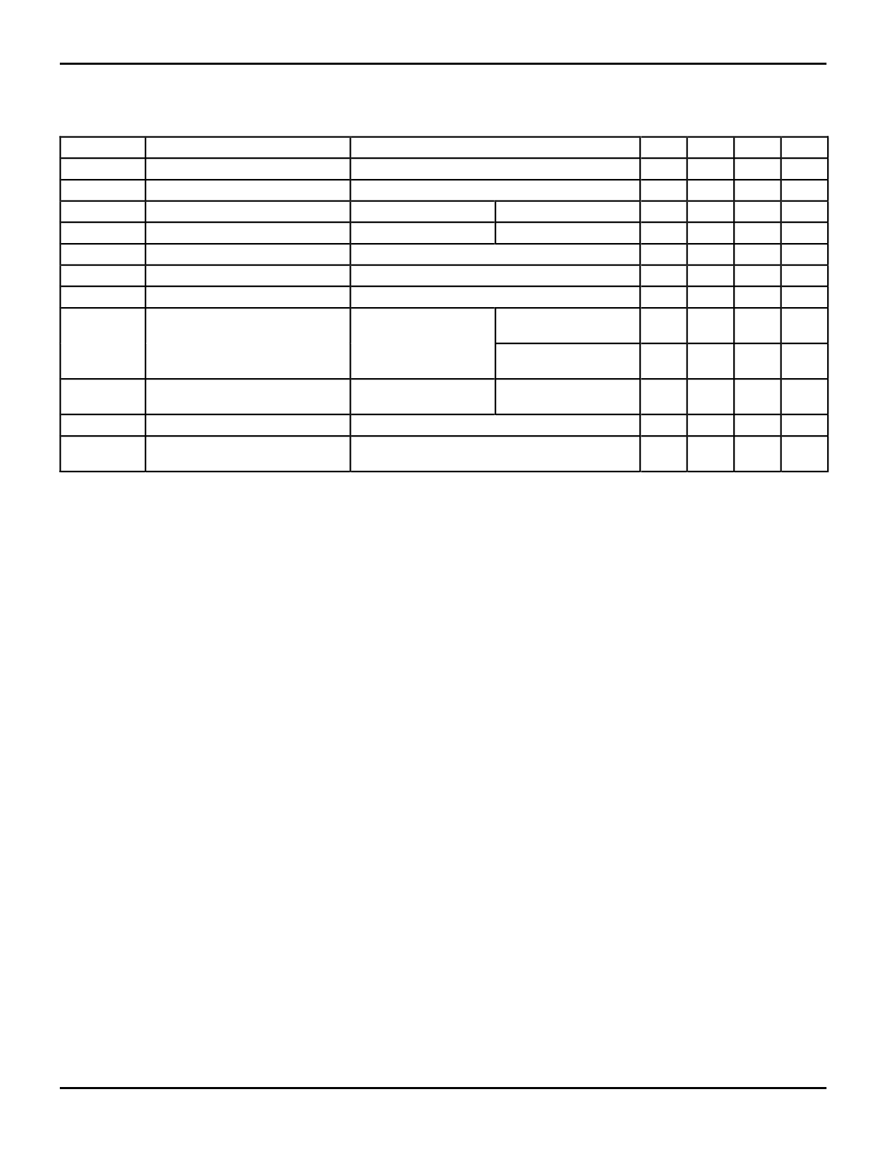
IDT54/74FCT138T/AT/CT
FAST CMOS 1-OF-8 DECODER-WITH ENABLE
MILITARY AND COMMERCIAL TEMPERATURE RANGES
DC ELECTRICAL CHARACTERISTICS OVER OPERATING RANGE
Following Conditions Apply Unless Otherwise Specified:
Commercial: TA = 0°C to +70°C, VCC = 5.0V ± 5%; Military: TA = –55°C to +125°C, VCC = 5.0V ± 10%
Symbol
VIH
Parameter
Input HIGH Level
Test Conditions(1)
Guaranteed Logic HIGH Level
Min. Typ.(2) Max. Unit
2.0 —
—
V
VIL
Input LOW Level
Guaranteed Logic LOW Level
—
— 0.8
V
II H
Input HIGH Current(4)
II L
Input LOW Current(4)
II
Input HIGH Current(4)
VCC = Max.
VI = 2.7V
VCC = Max.
VI = 0.5V
VCC = Max., VI = VCC (Max.)
—
—
±1 µA
—
—
±1 µA
—
—
±1 µA
VIK
Clamp Diode Voltage
VCC = Min., IN = –18mA
— –0.7 –1.2 V
IOS
Short Circuit Current
VCC = Max.(3), VO = GND
–60 –120 –225 mA
VOH
Output HIGH Voltage
VOL
Output LOW Voltage
VH
Input Hysteresis
VCC = Min.
VIN = VIH or VIL
VCC = Min.
VIN = VIH or VIL
IOH = –6mA MIL.
2.4 3.3 —
V
IOH = –8mA COM'L.
IOH = –12mA MIL.
2.0 3.0 —
V
IOH = –15mA COM'L.
IOL = 32mA MIL.
— 0.3 0.5
V
IOL = 48mA COM'L.
—
— 200 — mV
ICC
Quiescent Power Supply Current VCC = Max.
— 0.01 1
VIN = GND or VCC
NOTES:
1. For conditions shown as Max. or Min., use appropriate value specified under Electrical Characteristics for the applicable device type.
2. Typical values are at VCC = 5.0V, +25°C ambient.
3. Not more than one output should be shorted at one time. Duration of the short circuit test should not exceed one second.
4. The test limit for this parameter is ±5µA at TA = –55°C.
mA
2570 tbl 05
6.3
3
Share Link: 