IRF6622 View Datasheet(PDF) - International Rectifier
Part Name
Description
Manufacturer
IRF6622 Datasheet PDF : 10 Pages
| |||
IRF6622
Static @ TJ = 25°C (unless otherwise specified)
Parameter
Min.
BVDSS
∆ΒVDSS/∆TJ
RDS(on)
Drain-to-Source Breakdown Voltage
25
Breakdown Voltage Temp. Coefficient –––
Static Drain-to-Source On-Resistance –––
–––
VGS(th)
∆VGS(th)/∆TJ
IDSS
Gate Threshold Voltage
Gate Threshold Voltage Coefficient
Drain-to-Source Leakage Current
1.35
–––
–––
–––
IGSS
Gate-to-Source Forward Leakage
–––
Gate-to-Source Reverse Leakage
–––
gfs
Forward Transconductance
55
Qg
Total Gate Charge
–––
Qgs1
Pre-Vth Gate-to-Source Charge
–––
Qgs2
Post-Vth Gate-to-Source Charge
–––
Qgd
Gate-to-Drain Charge
–––
Qgodr
Gate Charge Overdrive
–––
Qsw
Switch Charge (Qgs2 + Qgd)
–––
Qoss
Output Charge
–––
RG
Gate Resistance
–––
td(on)
Turn-On Delay Time
–––
tr
Rise Time
–––
td(off)
Turn-Off Delay Time
–––
tf
Fall Time
–––
Ciss
Input Capacitance
–––
Coss
Output Capacitance
–––
Crss
Reverse Transfer Capacitance
–––
Diode Characteristics
Parameter
Min.
IS
Continuous Source Current
–––
(Body Diode)
ISM
Pulsed Source Current
–––
(Body Diode) d
VSD
Diode Forward Voltage
–––
trr
Reverse Recovery Time
–––
Qrr
Reverse Recovery Charge
–––
Typ.
–––
17
4.9
6.8
1.8
-5.9
–––
–––
–––
–––
–––
11
2.5
1.6
3.8
3.1
5.4
7.7
1.8
13
87
14
5.6
1450
380
210
Typ.
–––
–––
–––
10
7.1
Max. Units
Conditions
–––
–––
6.3
8.9
2.35
V VGS = 0V, ID = 250µA
mV/°C Reference to 25°C, ID = 1mA
mΩ VGS = 10V, ID = 15A c
VGS = 4.5V, ID = 12A c
V VDS = VGS, ID = 25µA
––– mV/°C
1.0
150
100
-100
–––
µA VDS = 20V, VGS = 0V
VDS = 20V, VGS = 0V, TJ = 125°C
nA VGS = 20V
VGS = -20V
S VDS = 13V, ID = 12A
17
–––
VDS = 13V
––– nC VGS = 4.5V
–––
ID = 12A
–––
See Fig. 15
–––
––– nC VDS = 16V, VGS = 0V
3.1 Ω
–––
VDD = 13V, VGS = 4.5V c
––– ns ID = 12A
–––
Clamped Inductive Load
–––
–––
VGS = 0V
––– pF VDS = 13V
–––
ƒ = 1.0MHz
Max. Units
Conditions
2.7
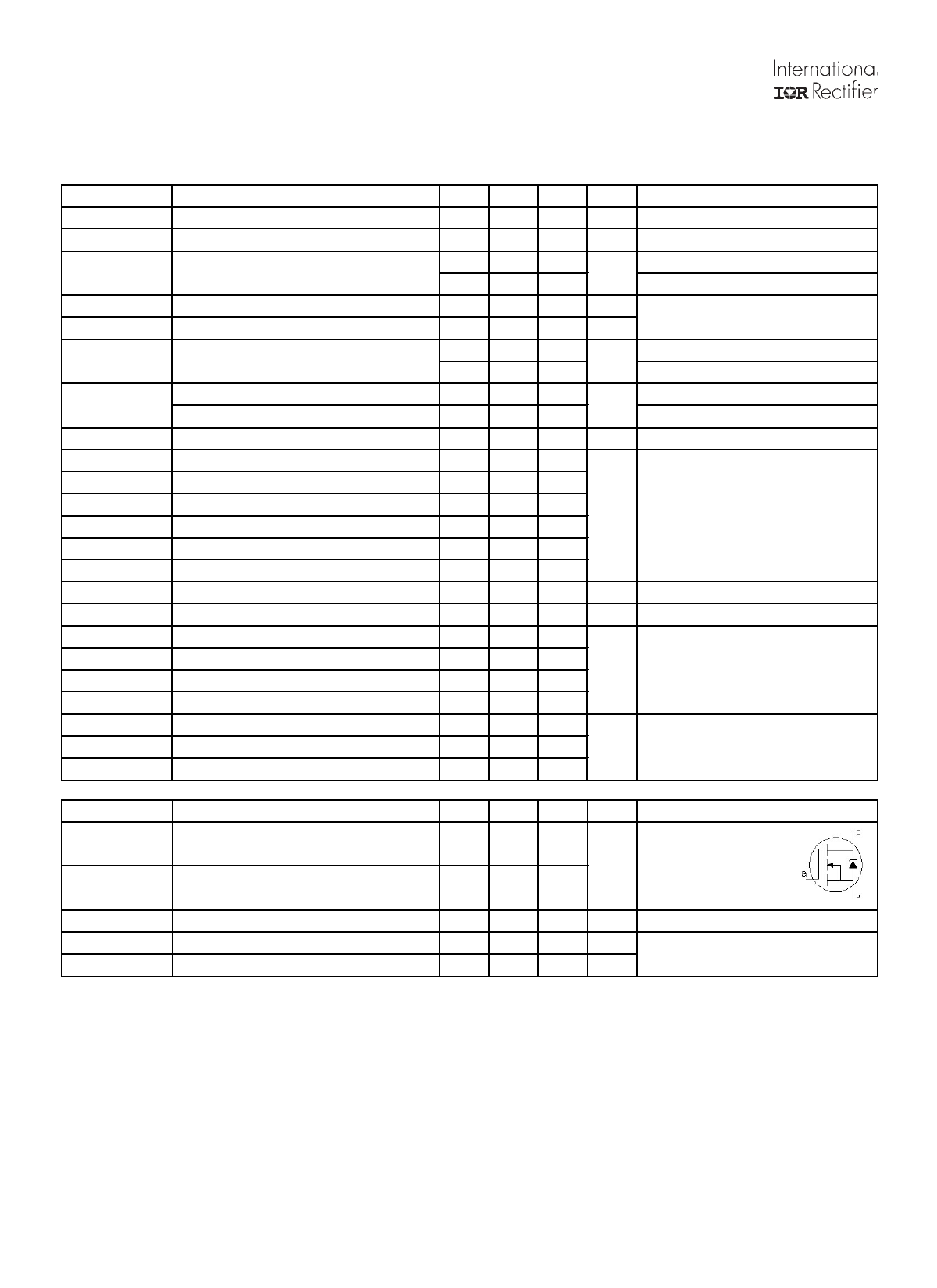
MOSFET symbol
A showing the
120
integral reverse
p-n junction diode.
1.0
V TJ = 25°C, IS = 12A, VGS = 0V c
15 ns TJ = 25°C, IF = 12A
11 nC di/dt = 500A/µs c
Notes:
Pulse width ≤ 400µs; duty cycle ≤ 2%.
Repetitive rating; pulse width limited by max. junction temperature.
2
www.irf.com
Share Link: 