ISL6236AIRZ-T View Datasheet(PDF) - Intersil
Part Name
Description
Manufacturer
ISL6236AIRZ-T
Intersil
ISL6236AIRZ-T Datasheet PDF : 37 Pages
| |||
ISL6236A
Adjustable-Output Feedback (Dual-Mode FB)
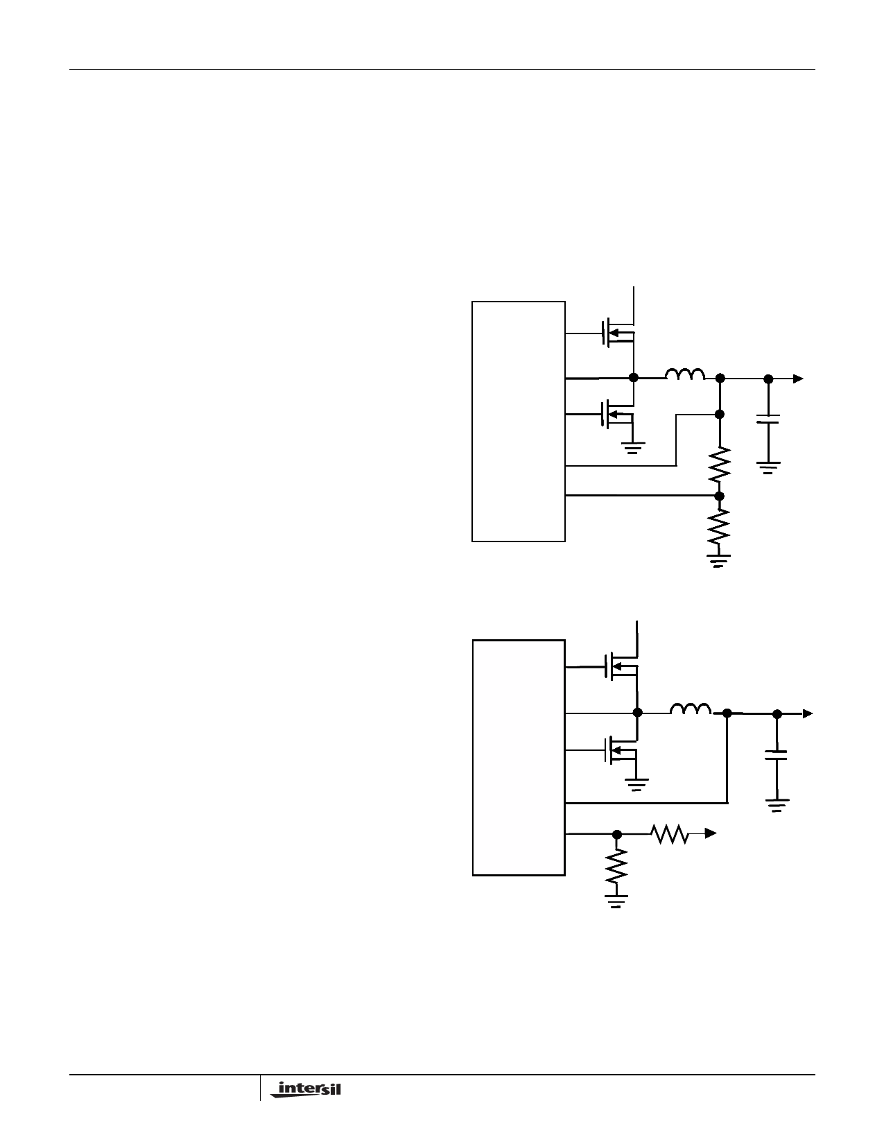
Connect FB1 to GND to enable the fixed 5V or tie FB1 to
VCC to set the fixed 1.5V output. Connect a resistive
voltage-divider at FB1 between OUT1 and GND to adjust the
respective output voltage between 0.7V and 5.5V
(Figure 77). Choose R2 to be approximately 10k and solve
for R1 using Equation 6.
R1
=
R2
⋅
⎛
⎜
⎝
V-----O----U----T----1-
VFB1
–
⎞
1⎟
⎠
(EQ. 6)
where VFB1 = 0.7V nominal.
Likewise, connect REFIN2 to VCC to enable the fixed 3.3V
or tie REFIN2 to VREF3 to set the fixed 1.05V output. Set
REFIN2 from 0 to 2.50V for SMPS2 tracking mode
(Figure 78).
R3
=
R4
⋅
⎛
⎝
------V----R--------
VOUT2
–
1⎠⎞
(EQ. 7)
where:
• VR = 2V nominal (if tied to REF)
or
• VR = 3.3V nominal (if tied to VREF3)
Design Procedure
Establish the input voltage range and maximum load current
before choosing an inductor and its associated ripple current
ratio (LIR). The following four factors dictate the rest of the
design:
1. Input Voltage Range. The maximum value (VIN(MAX))
must accommodate the maximum AC adapter voltage.
The minimum value (VIN(MIN)) must account for the
lowest input voltage after drops due to connectors, fuses
and battery selector switches. Lower input voltages result
in better efficiency.
2. Maximum Load Current. The peak load current
(ILOAD(MAX)) determines the instantaneous component
stress and filtering requirements and thus drives output
capacitor selection, inductor saturation rating and the
design of the current-limit circuit. The continuous load
current (ILOAD) determines the thermal stress and drives
the selection of input capacitors, MOSFETs and other
critical heat-contributing components.
3. Switching Frequency. This choice determines the basic
trade-off between size and efficiency. The optimal
frequency is largely a function of maximum input voltage
and MOSFET switching losses.
4. Inductor Ripple Current Ratio (LIR). LIR is the ratio of the
peak-peak ripple current to the average inductor current.
Size and efficiency trade-offs must be considered when
setting the inductor ripple current ratio. Low inductor
values cause large ripple currents, resulting in the
smallest size, but poor efficiency and high output noise.
Also, total output ripple above 3.5% of the output
regulation will cause controller to trigger out-of-bound
condition. The minimum practical inductor value is one
that causes the circuit to operate at critical conduction
(where the inductor current just touches zero with every
cycle at maximum load). Inductor values lower than this
grant no further size-reduction benefit.
The ISL6236A pulse-skipping algorithm (SKIP# = GND)
initiates skip mode at the critical conduction point, so the
inductor's operating point also determines the load
current at which PWM/PFM switchover occurs. The
optimum LIR point is usually found between 25% and
50% ripple current.
VIN
UGATE1
Q3
ISL6236A
LGATE1
Q4
OUT1
OUT1
R1
FB1
R2
FIGURE 77. SETTING VOUT1 WITH A RESISTOR DIVIDER
VIN
UGAUTGEA2TE2
Q1
ISL88732
ISL68283763A3
ISL88734
LGALTGEA2TE2
Q2
OUT2
VOOUUTOTU2T2
REFRINFE2BFIN2
R4
VR
R3
FIGURE 78. SETTING VOUT2 WITH A VOLTAGE DIVIDER FOR
TRACKING
32
FN6453.0
March 14, 2007
Share Link: 