KTY81/122 View Datasheet(PDF) - NXP Semiconductors.
Part Name
Description
Manufacturer
KTY81/122 Datasheet PDF : 15 Pages
| |||
NXP Semiconductors
KTY81 series
Silicon temperature sensors
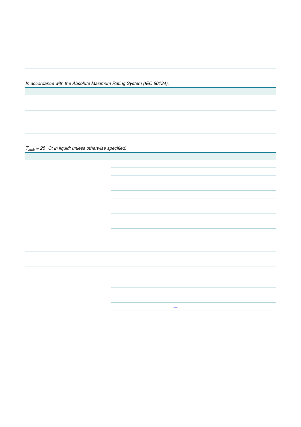
5. Limiting values
Table 5. Limiting values
In accordance with the Absolute Maximum Rating System (IEC 60134).
Symbol Parameter
Conditions
Min
Isen(cont) continuous sensor current in free air; Tamb = 25 °C
-
in free air; Tamb = 150 °C
-
Tamb
ambient temperature
−55
6. Characteristics
Max
Unit
10
mA
2
mA
+150
°C
Table 6. Characteristics
Tamb = 25 °C; in liquid; unless otherwise specified.
Symbol Parameter
Conditions
Min
Typ
Max
Unit
R25
sensor resistance
Isen(cont) = 1 mA
KTY81/110
990
-
1 010
Ω
KTY81/120
980
-
1 020
Ω
KTY81/121
980
-
1 000
Ω
KTY81/122
1 000
-
1 020
Ω
KTY81/150
950
-
1 050
Ω
KTY81/210
1 980
-
2 020
Ω
KTY81/220
1 960
-
2 040
Ω
KTY81/221
1 960
-
2 000
Ω
KTY81/222
2 000
-
2 040
Ω
KTY81/250
1 900
-
2 100
Ω
TC
temperature coefficient
-
0.79
-
%/K
R100/R25
R−55/R25
∆R25
resistance ratio
resistance ratio
drift of sensor resistance at
25 °C
Tamb = 100 °C and 25 °C
Tamb = −55 °C and 25 °C
10000 h continuous
operation; Tamb = 150 °C
KTY81/1 series
1.676
0.480
1.696
0.490
1.716
0.500
-
1.6
-
Ω
KTY81/2 series
-
3.2
-
Ω
τth
thermal time constant
in still air
in still liquid
[1] -
30
-
s
[1] -
5
-
s
in flowing liquid
[1] -
3
-
s
[1] The thermal time constant is the time taken for the sensor to reach 63.2 % of the total temperature difference. For example, if a sensor
with a temperature of 25 °C is moved to an environment with an ambient temperature of 100 °C, the time for the sensor to reach a
temperature of 72.4 °C is the thermal time constant.
KTY81_SER_5
Product data sheet
Rev. 05 — 25 April 2008
© NXP B.V. 2008. All rights reserved.
3 of 15
Share Link: 