MAX6412UK View Datasheet(PDF) - Maxim Integrated
Part Name
Description
Manufacturer
MAX6412UK
Maxim Integrated
MAX6412UK Datasheet PDF : 12 Pages
| |||
MAX6412‚ÄďMAX6420
Low-Power, Single/Dual-Voltage ¬ĶP Reset Circuits
with Capacitor-Adjustable Reset Timeout Delay
VMON_TH
VCC
MAX6420
ONLY
VCC
LASER-TRIMMED
RESISTORS
RL
(RESET)
RESET
RESET
CIRCUITRY
1.26V
¬ĶP
R1
R2
CSRT
RESET IN
GND
SRT
MAX6418
MAX6419
MAX6420
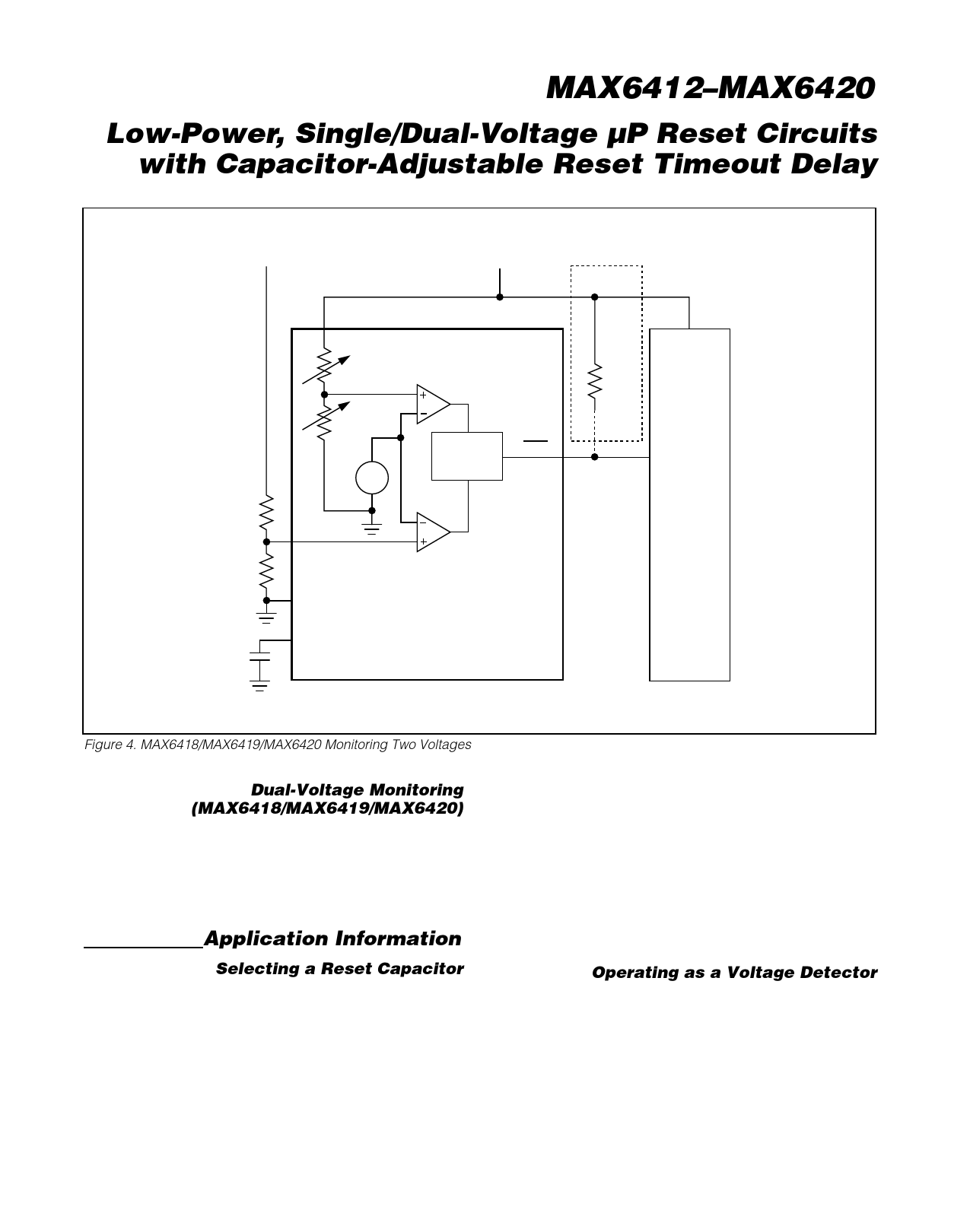
Figure 4. MAX6418/MAX6419/MAX6420 Monitoring Two Voltages
Dual-Voltage Monitoring
(MAX6418/MAX6419/MAX6420)
The MAX6418/MAX6419/MAX6420 contain both facto-
ry-trimmed threshold voltages and an adjustable reset
threshold input, allowing the monitoring of two voltages,
VCC and VMON_TH (see Figure 4). Reset is asserted
when either of the voltages falls below its respective
threshold voltage.
Application Information
Selecting a Reset Capacitor
The reset timeout period is adjustable to accommodate
a variety of ¬ĶP applications. Adjust the reset timeout
period (tRP) by connecting a capacitor (CSRT) between
SRT and ground. Calculate the reset timeout capacitor
as follows:
CSRT = (tRP - 275¬Ķs) / (2.71 106)
where tRP is in seconds and CSRT is in Farads
The reset delay time is set by a current/capacitor-con-
trolled ramp compared to an internal 0.65V reference.
An internal 240nA ramp current source charges the
external capacitor. The charge to the capacitor is
cleared when a reset condition is detected. Once the
reset condition is removed, the voltage on the capacitor
ramps according to the formula: dV/dt = I/C. The CSRT
capacitor must ramp to 0.65V to deassert the reset.
CSRT must be a low-leakage (<10nA) type capacitor,
ceramic is recommended.
Operating as a Voltage Detector
The MAX6412‚ÄďMAX6420 can be operated in a voltage
detector mode by leaving SRT unconnected. The reset
delay times for VCC rising above or falling below the
threshold are not significantly different. The reset output
is deasserted smoothly without false pulses.
Maxim Integrated
7
Share Link: 