NCP3012 View Datasheet(PDF) - ON Semiconductor
Part Name
Description
Manufacturer
NCP3012 Datasheet PDF : 26 Pages
| |||
NCP3012
Startup and Shutdown
Once enable is asserted the device begins its startup
process. Closed−loop soft−start begins after a 400 ms delay
wherein the boost capacitor is charged, and the current limit
threshold is set. During the 400 ms delay the OTA output is
set to just below the valley voltage of the internal ramp. This
is done to reduce delays and to ensure a consistent pre
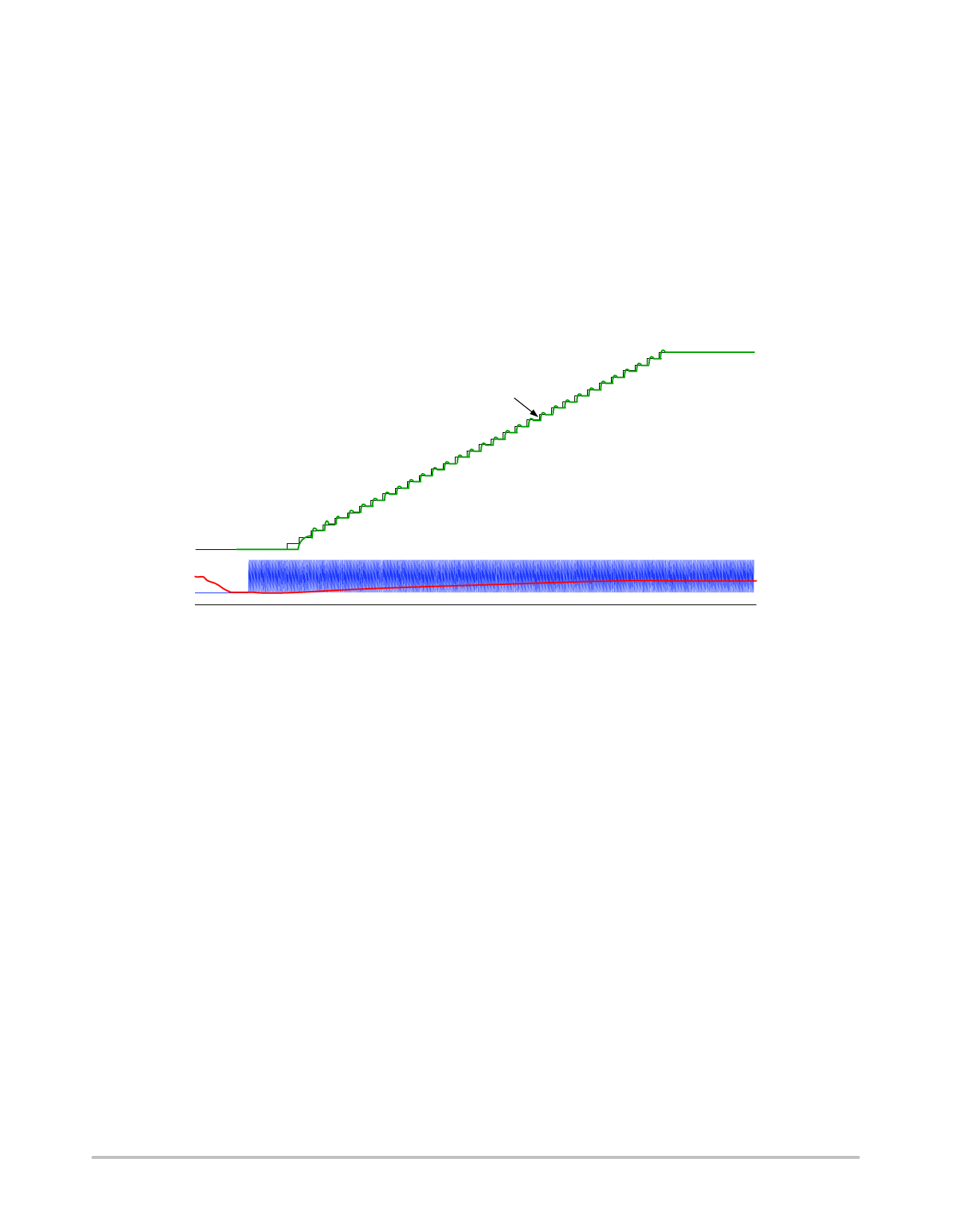
soft−start condition. The device increases the internal
reference from 0 V to 0.8 V in 32 discrete steps while
maintaining closed loop regulation at each step. Some
overshoot may be evident at the start of each step depending
on the voltage loop phase margin and bandwidth. See
Figure 19. The total soft−start time is 14 ms.
The soft−stop process begins once the EN pin voltage
goes below the input low threshold. Soft−stop decreases the
internal reference from 0.8 V − 0 V in 32 steps as with
Soft−Start. Soft−Stop finishes with one “last” high side gate
pulse at half the period of the prior pulse. This helps ensure
positive inductor current following turn off at light loads,
which prevents negative output voltage.
Enable low during Soft−Start will result in Soft−Stop
down counting from that step. Likewise, Enable high during
Soft−Stop will result in Soft−Start up counting from that
step.
0.8 V Output Voltage
25 mV Steps
32 Voltage Steps
Internal Reference Voltage
Internal Ramp
OTA Output
0 .7V
0V
Figure 19. Soft−Start Details
http://onsemi.com
11
Share Link: 