OP497 View Datasheet(PDF) - Analog Devices
Part Name
Description
Manufacturer
OP497 Datasheet PDF : 16 Pages
| |||
OP497
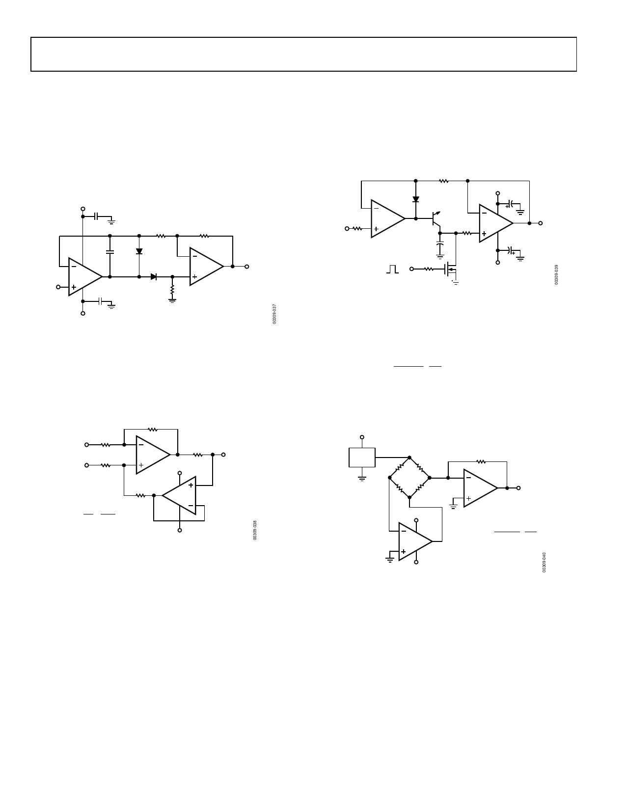
APPLICATIONS CIRCUIT
PRECISION ABSOLUTE VALUE AMPLIFIER
The circuit in Figure 36 is a precision absolute value amplifier
with an input impedance of 30 MΩ. The high gain and low
TCVOS of the OP497 ensure accurate operation with microvolt
input signals. In this circuit, the input always appears as a common-
mode signal to the op amps. The CMR of the OP497 exceeds
120 dB, yielding an error of less than 2 ppm.
+15V
C2
0.1µF
R1
R3
1kΩ
1kΩ
C1
30pF
2
8
1/4
1
OP497
VIN 3
C3
4 0.1µF
D1
1N4148
D2
1N4148
6
1/4
7
OP497
5
0V < VOUT < 10V
R2
2kΩ
–15V
Figure 36. Precision Absolute Value Amplifier
PRECISION CURRENT PUMP
Maximum output current of the precision current pump shown
in Figure 37 is ±10 mA. Voltage compliance is ±10 V with ±15 V
supplies. Output impedance of the current transmitter exceeds
3 MΩ with linearity better than 16 bits.
R1
10kΩ
–
VIN
R2
10kΩ
+
R3
10kΩ
2
1/4
OP497
3
R5
1
10kΩ
+15V
IOUT
±10mA
R4
10kΩ
IOUT
=
VIN
R5
= VIN
100Ω
=
10mA/V
8
5
7
1/4
OP497
6
4
–15V
Figure 37. Precision Current Pump
PRECISION POSITIVE PEAK DETECTOR
In Figure 38, the CH must be of polystyrene, Teflon®, or
polyethylene to minimize dielectric absorption and leakage.
The droop rate is determined by the size of CH and the bias
current of the OP497.
2
1/4
1
VIN 1kΩ 3 OP497
1kΩ
1N4148
+15V
0.1µF
2N930
CH +
6
8
1/4
7
1kΩ 5 OP497
4 0.1µF
VOUT
1kΩ
RESET
–15V
Figure 38. Precision Positive Peak Detector
SIMPLE BRIDGE CONDITIONING AMPLIFIER
Figure 39 shows a simple bridge conditioning amplifier using
the OP497. The transfer function is
VOUT
= VREF
⎜⎛
⎜⎝
R
ΔR
+ ΔR
⎟⎞
⎟⎠
RF
R
The REF43 provides an accurate and stable reference voltage for
the bridge. To maintain the highest circuit accuracy, RF should
be 0.1% or better with a low temperature coefficient.
+5V
2
REF43 6 2.5V VREF
R
R
4
R
R + ΔR
RF
2
1/4
1
OP497
3
VOUT
+5V
6
8
1/4
7
5 OP497
4
( ) VOUT = VREF
ΔR
R + ΔR
RF
R
–5V
Figure 39. Simple Bridge Conditioning Amplifier Using the OP497
Rev. E | Page 12 of 16
Share Link: 