PCA9545AD View Datasheet(PDF) - Philips Electronics
Part Name
Description
Manufacturer
PCA9545AD Datasheet PDF : 27 Pages
| |||
Philips Semiconductors
PCA9545A
4-channel I2C switch with interrupt logic and reset
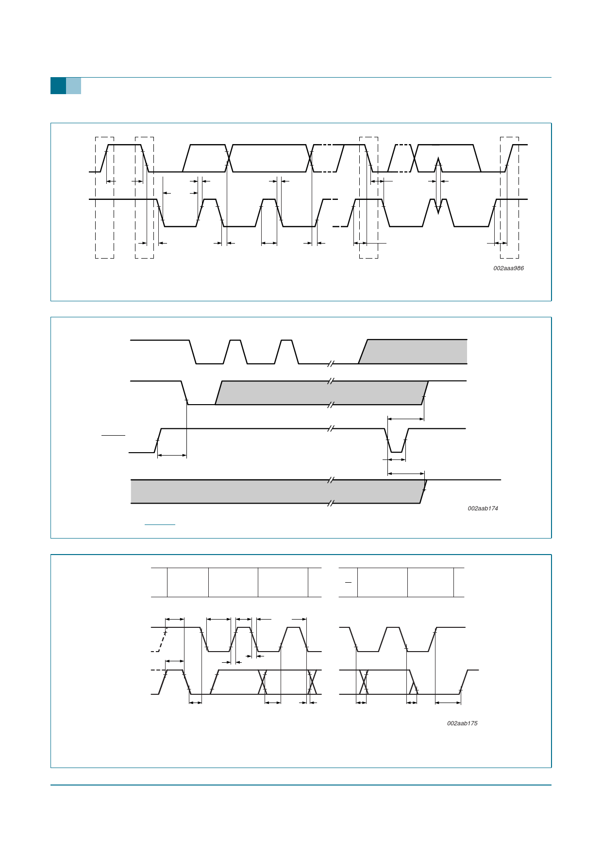
SDA
tBUF
SCL
tr
tLOW
tHD;STA
P
S
tHD;DAT
tf
tHIGH
tSU;DAT
Fig 15. Definition of timing on the I2C-bus
tHD;STA
tSP
tSU;STA
Sr
tSU;STO
P
002aaa986
START
SCL
ACK or read cycle
SDA
30 %
RESET 50 %
LEDx
tREC;STA
Fig 16. Definition of RESET timing
trst
50 %
tw(rst)L
50 %
trst
50 %
LED off
002aab174
protocol
START
condition
(S)
bit 7
MSB
(A7)
bit 6
(A6)
SCL
SDA
tSU;STA
tBUF
tLOW tHIGH
1/fSCL
tr
tf
bit 0 acknowledge
(R/W)
(A)
STOP
condition
(P)
tHD;STA
Rise and fall times, refer to VIL and VIH.
Fig 17. I2C-bus timing diagram
9397 750 14311
Product data sheet
tSU;DAT tHD;DAT
tVD;DAT
Rev. 03 — 3 March 2005
tVD;ACK
tSU;STO
002aab175
© Koninklijke Philips Electronics N.V. 2005. All rights reserved.
17 of 27
Share Link: 