ST8024CD View Datasheet(PDF) - STMicroelectronics
Part Name
Description
Manufacturer
ST8024CD Datasheet PDF : 23 Pages
| |||
ST8024
If the card is in the reader (this is the case if PRES or PRES is active), the system microcontroller can start
a card session by pulling CMDVCC LOW. The following sequence then occurs (see Fig.6):
1. CMDVCC is pulled LOW and the internal oscillator changes to its high frequency (t0).
2. The voltage doubler is started (between t0 and t1).
3. VCC rises from 0 to 5 V (or 3 V) with a controlled slope (t2 = t1 + 1.5 x T) where T is 64 times the period
of the internal oscillator (approximately 25 µs).
4. I/O, AUX1 and AUX2 are enabled (t3 = t1 + 4T) (these were pulled LOW until this moment).
5. CLK is applied to the C3 contact of the card reader (t4).
6. RST is enabled (t5 = t1 + 7T).
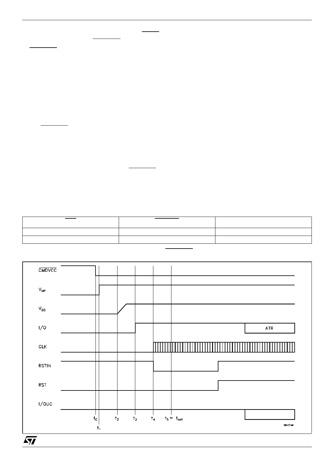
The clock may be applied to the card using the following sequence (see Fig.5):
1. Set RSTIN HIGH.
2. Set CMDVCC LOW.
3. Reset RSTIN LOW between t3 and t5; CLK will start at this moment.
4. RST remains LOW until t5, when RST is enabled to be the copy of RSTIN.
5. After t5, RSTIN has no further affect on CLK; this allows a precise count of CLK pulses before toggling
RST.
If the applied clock is not needed, then CMDVCC may be set LOW with RSTIN LOW. In this case, CLK will
start at t3 (minimum 200 ns after the transition on I/O), and after t5, RSTIN may be set HIGH in order to
obtain an Answer To Request (ATR) from the card.
Activation should not be performed with RSTIN held permanently HIGH.
Table 21: Card presence indicator
OFF
H
L
CMDVCC
H
H
INDICATION
card present
card not present
Figure 5: Activation sequence using RSTIN and CMDVCC
13/23
Share Link: 