WM8750-EV1M View Datasheet(PDF) - Wolfson Microelectronics plc
Part Name
Description
Manufacturer
WM8750-EV1M Datasheet PDF : 48 Pages
| |||
WM8750-EV1M
LINKS AND JUMPERS
H1
H2
SW36
J18 (BCLK)
J20 (ADCLRC)
J25 (DACLRC)
J23
J32, J33, J34 and J35
SW3
LINK/JUMPER STATUS
No jumpers in place
No jumpers in place
Pins 2 and 3 SHORT
SHORT
SHORT
SHORT
SHORT
OPEN
SW4
Pins 1 and 2 SHORT
SW1, SW2
Pins 2 and 3 SHORT
SW5, SW7
Pins 2 and 3 SHORT
SW8, SW9
Pins 2 and 3 SHORT
SW27, SW28
Pins 2 and 3 SHORT
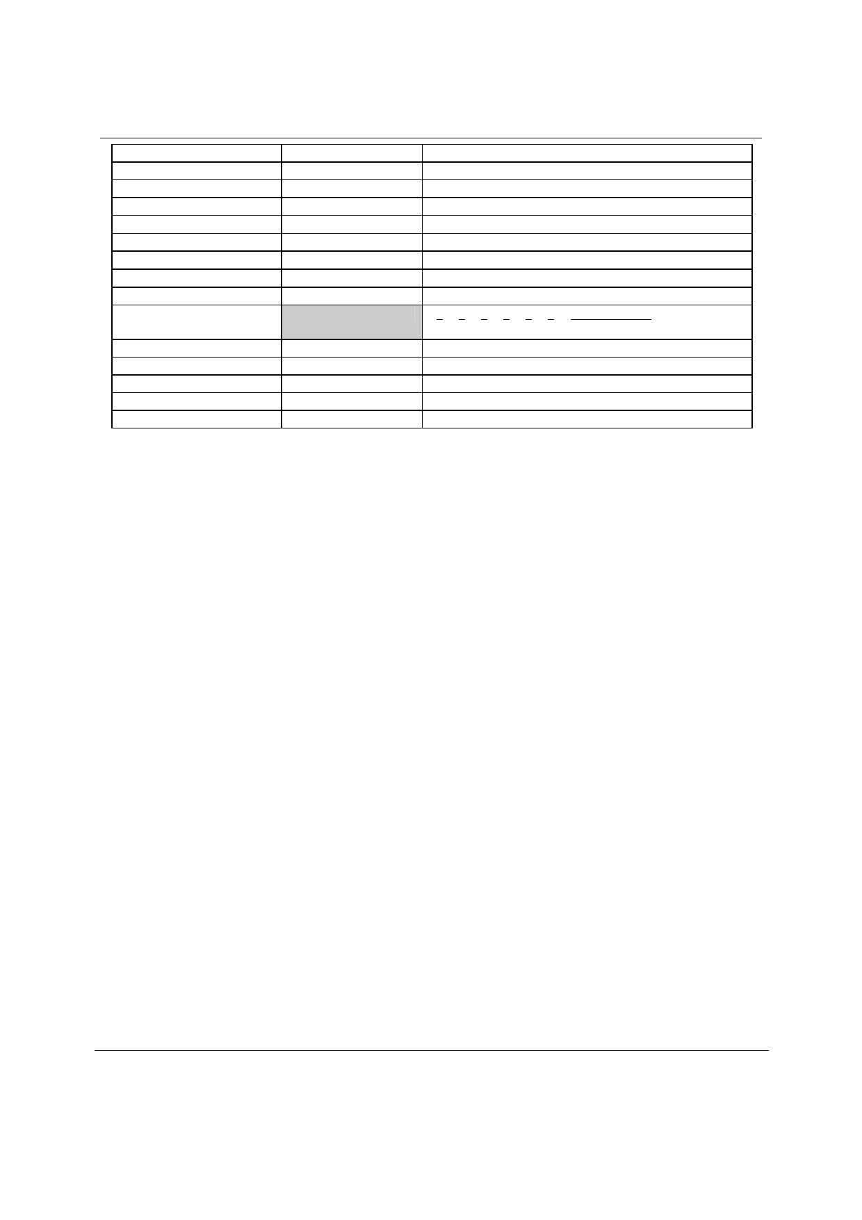
Table 12 Line Setup Jumper Setup (Slave Mode)
DESCRIPTION
DAC clocks and data input
ADC clocks and data output
Connects to GND for HP output reference
Slave mode
Slave mode
Slave mode
Slave mode
OUT signals are AC coupled
1 2 3 4 5 6 DATA FORMAT
1 0 0 1 0 0 I2S Compatible
3-wire (SPI) Control Mode
Line Input Select (Phono Socket)
Line Input Select (Phono Socket)
Line Input Select (Phono Socket)
Line Output Select (Phono Socket)
w
Rev 2.0, February 2005
18
Share Link: 