LT1611 View Datasheet(PDF) - Linear Technology
Part Name
Description
Manufacturer
LT1611 Datasheet PDF : 12 Pages
| |||
U
OPERATIO
Capacitors
As described previously, ceramic capacitors can be used
with the LT1611 provided loop stability is considered. For
lower cost applications, small tantalum units can be used.
A value of 22µF is acceptable, although larger capacitance
values can be used. ESR is the most important parameter
in selecting an output capacitor. The “flying” capacitor (C2
in the schematic figures) should be a 1µF ceramic type. An
X5R or X7R dielectric should be used to avoid capacitance
decreasing severely with applied voltage. The input by-
pass capacitor is less critical, and either tantalum or
LT1611
ceramic can be used with little trade-off in circuit perfor-
mance. Some capacitor types appropriate for use with the
LT1611 are listed in Table 2.
Diodes
A Schottky diode is recommended for use with the LT1611.
The Motorola MBR0520 is a very good choice. Where the
input to output voltage differential exceeds 20V, use the
MBR0530 ( a 30V diode). If cost is more important than
efficiency, a 1N4148 can be used, but only at low current
loads.
Table 1. Inductor Vendors
VENDOR
PHONE
Sumida
(847) 956-0666
Murata
Coiltronics
(404) 436-1300
(407) 241-7876
Table 2. Capacitor Vendors
VENDOR
PHONE
Taiyo Yuden (408) 573-4150
AVX
(803) 448-9411
Murata
(404) 436-1300
URL
www.sumida.com
www.murata.com
www.coiltronics.com
PART
CLS62-22022
CD43-470
LQH3C-220
CTX20-1
COMMENT
22µH Coupled
47µH
22µH, 2mm Height
20µH Coupled, Low DCR
URL
www.t-yuden.com
www.avxcorp.com
www.murata.com
PART
Ceramic Caps
Ceramic Caps
Tantalum Caps
Ceramic Caps
COMMENT
X5R Dielectric
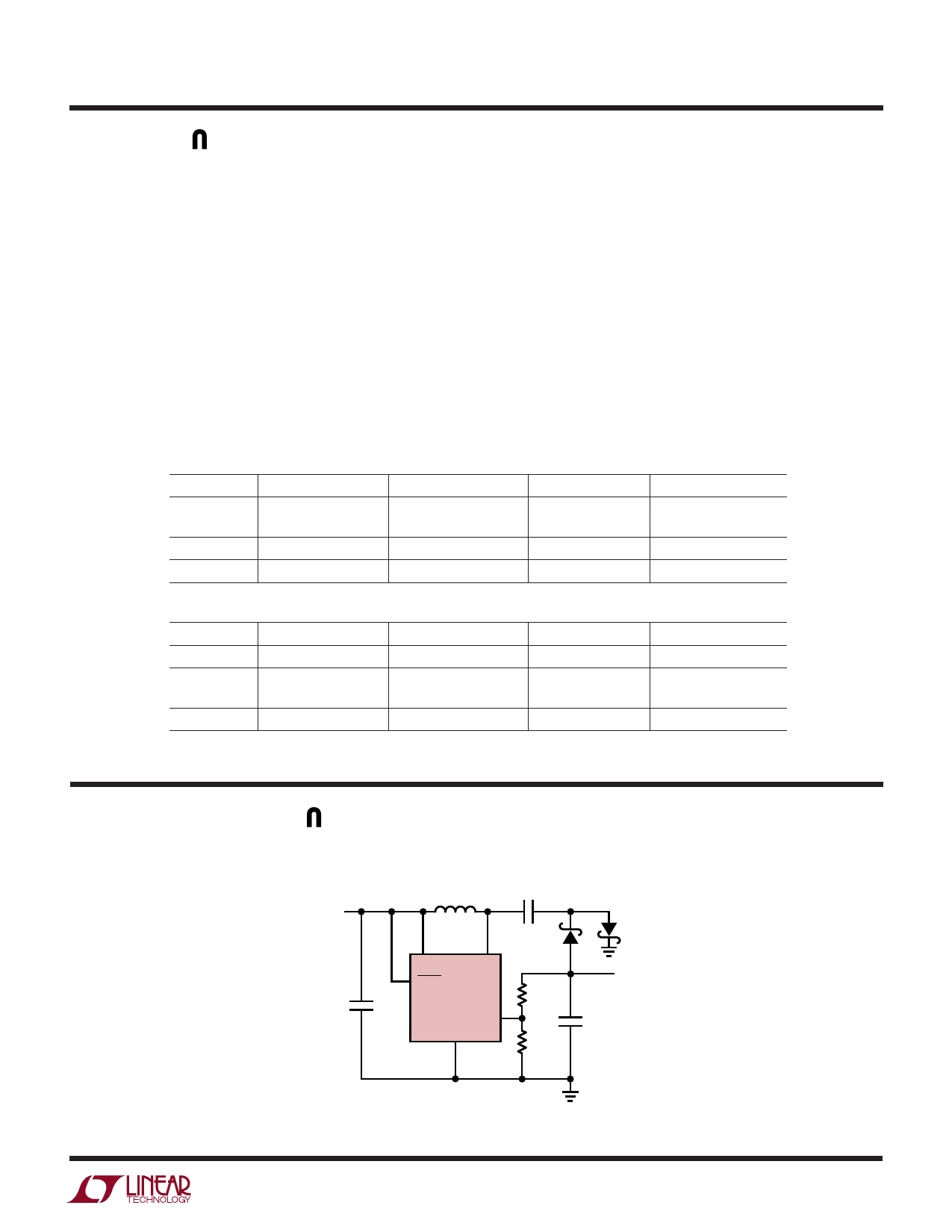
TYPICAL APPLICATIO S
“Charge Pump” Inverting DC/DC Converter
L1
10µH
C2
1µF
3.3V
D1
D2
VIN
SW
SHDN
C1
LT1611
1µF
NFB
GND
29.4k
10k
–5V
70mA
C3
22µF
C1, C2: TAIYO YUDEN LMK212BJ105MG
C3: TAIYO YUDEN JMK325BJ226MM
D1, D2: MBR0520
L1: MURATA LQH3C-100
1611 TA02
Information furnished by Linear Technology Corporation is believed to be accurate and reliable.
However, no responsibility is assumed for its use. Linear Technology Corporation makes no represen-
tation that the interconnection of its circuits as described herein will not infringe on existing patent rights.
11
Share Link: 