BMI-C-001 View Datasheet(PDF) - Unspecified
Part Name
Description
Manufacturer
BMI-C-001 Datasheet PDF : 26 Pages
| |||
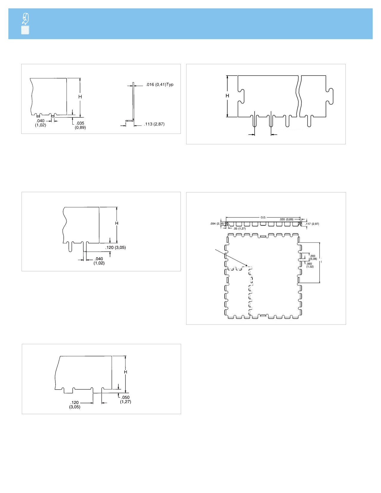
PIN STYLE 2.
Surface Mount Tab
.130 to 1.000
(3,3 to 25,4)
Under Cover
Height Range
STANDARD DESIGN SHIELDS AND CONTACTS
FIGURE 2.
Pitch Selection Placement and Corner Locking Feature
.130 to 1.000
(3,3 to 25,4)
Under Cover
Height Range
Any pitch (P) with minimum
of .200 (5,08)
PIN STYLE 3.
Through Hole
.130 to 1.000
(3,3 to 25,4)
Under Cover
Height Range
FIGURE 3.
Cover Detail
Standard cover material thickness 0.010" (0,25 mm) tin plated
phosphor bronze, in coated steel or stainless steel
Phantom
lines indicate
optional
L-shaped
configuration
Type on
random
locations
PIN STYLE 4.
Flush Surface Mount
.130 to 1.000
(3,3 to 25,4)
Under Cover
Height Range
4 www.lairdtech.com
All dimensions shown are in inches (millimeters) unless otherwise specified.
Share Link: 