MAX8952 View Datasheet(PDF) - Maxim Integrated
Part Name
Description
Manufacturer
MAX8952 Datasheet PDF : 31 Pages
| |||
MAX8952
2.5A Step-Down Regulator
with Remote Sense in 2mm x 2mm WLP
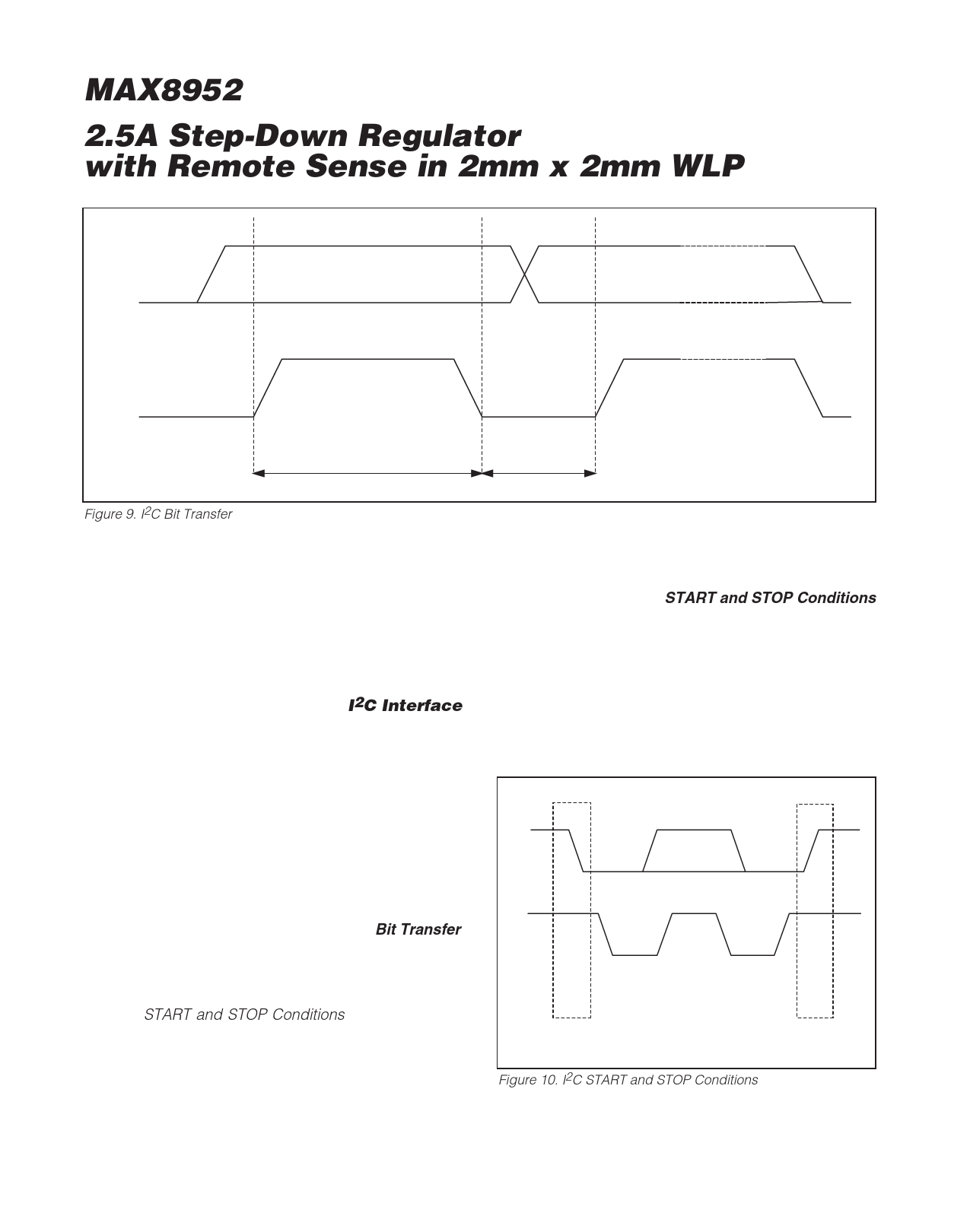
SDA
SCL
Figure 9. I2C Bit Transfer
DATA LINE STABLE DATA VALID
CHANGE OF DATA ALLOWED
die temperature in excess of +160°C (typ), the
DC-DC step-down regulator is shut down, allowing the
IC to cool. The DC-DC step-down regulator is turned on
again after the junction cools by 20°C (typ), resulting in
a pulsed output during continuous thermal-overload
conditions.
During thermal overload, the I2C interface remains
active and all register values are maintained.
I2C Interface
An I2C-compatible, 2-wire serial interface controls the
step-down converter output voltage, ramp rate, operat-
ing mode, and synchronization. The serial bus consists
of a bidirectional serial-data line (SDA) and a serial-
clock input (SCL). The master initiates data transfer on
the bus and generates SCL to permit data transfer.
I2C is an open-drain bus. SDA and SCL require pullup
resistors (500Ω or greater). Optional (24Ω) in series
with SDA and SCL protect the device inputs from high-
voltage spikes on the bus lines. Series resistors also
minimize crosstalk and undershoot on bus signals.
Bit Transfer
One data bit is transferred during each SCL clock
cycle. The data on SDA must remain stable during the
high period of the SCL clock pulse (see Figure 9).
Changes in SDA while SCL is high are control signals
(see the START and STOP Conditions section for more
information).
Each transmit sequence is framed by a START (S) con-
dition and a STOP (P) condition. Each data packet is 9
bits long; 8 bits of data followed by the acknowledge
bit. The IC supports data transfer rates with SCL fre-
quencies up to 400kHz.
START and STOP Conditions
When the serial interface is inactive, SDA and SCL idle
high. A master device initiates communication by
issuing a START condition. A START condition is a
high-to-low transition on SDA with SCL high. A STOP
condition is a low-to-high transition on SDA, while SCL
is high (Figure 10).
A START condition from the master signals the begin-
ning of a transmission to the IC. The master terminates
transmission by issuing a not acknowledge followed by
SDA
SCL
START
CONDITION
Figure 10. I2C START and STOP Conditions
STOP
CONDITION
16
Maxim Integrated
Share Link: 