NTE7116 View Datasheet(PDF) - NTE Electronics
Part Name
Description
Manufacturer
NTE7116 Datasheet PDF : 5 Pages
| |||
AC Characteristics (Cont’d): (VS = 8.5V, TA = +25°C, AC Conditions: (1) Input signal (Vi) of
815mVP–P for L = 1, R = 1 (mono), fm = 1kHz (80% modulation); (2)
MUX input signal (Vi) of 1.2VP–P for L = 1, R = 0 and no dbx, fm = 1kHz
(stereo) and Vpilot = 200VP–P; (3) S1 open, unless specified (without
L – R filter), VCO measured with an external IF roll–off network (–2dB
at 31.5kHz = 2fH) at the input. All the above conditions apply unless
otherwise specified)
Parameter
Symbol
Test Conditions
Min Typ Max Unit
Source Selector (Cont’d) (Pin6)
Switching Level (External Selected)
Voltage
VIH
Current
IIH Vi = VP
Muting Circuit (Pin7)
2
–
VP V
–
0.1
1.0 µA
Input Voltage
Input Current
VIL Mute ON
VIH Mute OFF
–IIL Mute ON, VIL = 0.8V
IIL Mute OFF, VIH = VP
–
–
0.8 V
2
–
VP V
–
10
25 µA
–
0.1
1.0 µA
Note 4. Intermodulation suppression (Beat Frequency Components (BFC)):
α2 =
VO (signal) (at 1kHz)
VO (spurious) (at 1kHz)
α3 =
VO (signal) (at 1kHz)
VO (spurious) (at 1kHz)
; fs = (2 x 8.367kHz) –fH
; fs = (3 x 10.823kHz) –2fH
measured with 100% modulated input signal: L = R; pilot signal = 200mVP–P; fm = 8.367 or
10.823kHz.
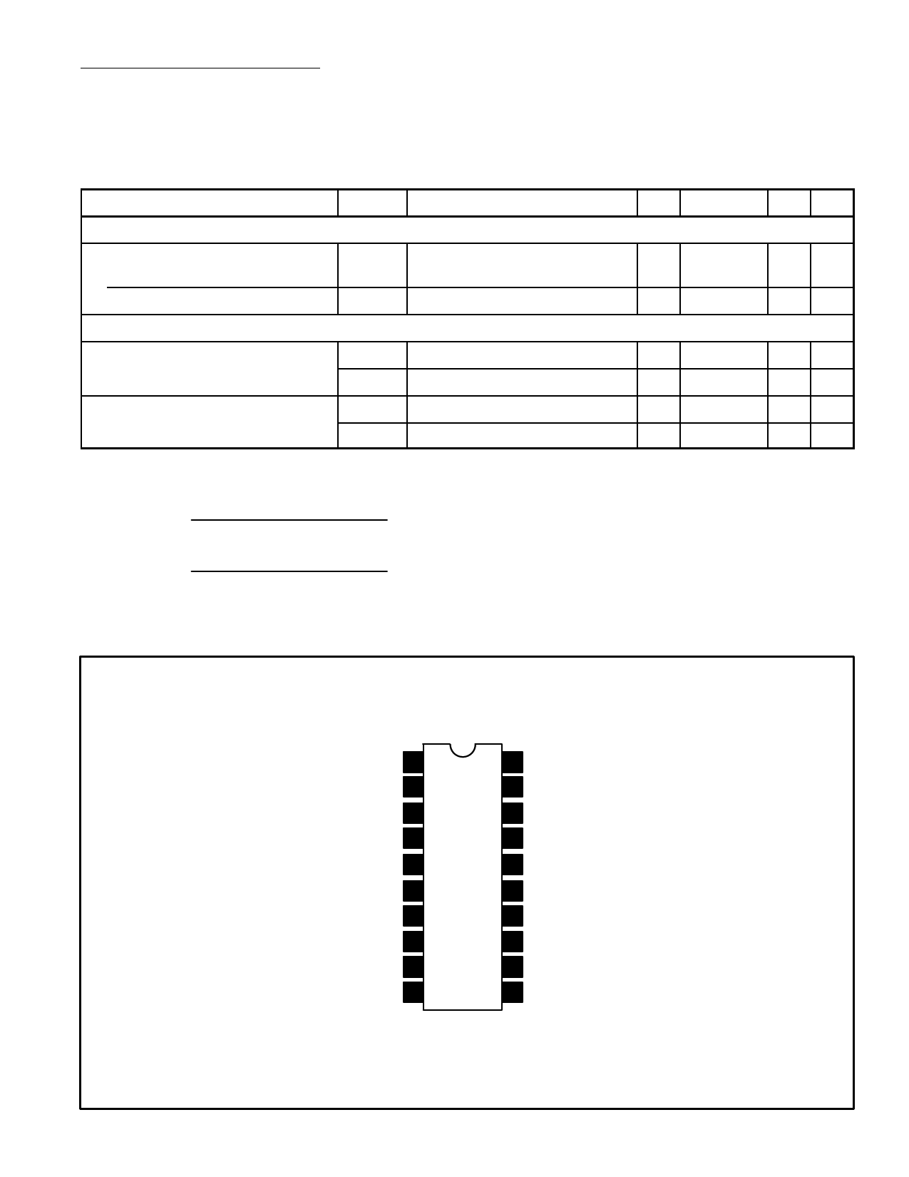
Pin Connection Diagram
Multiplexer Input 1
Pilot Presence Det 2
LED Driver Output 3
VCO 4
VP 5
Source Selector Input 6
Mute Input 7
Input 2, Left 8
Input 2, Right 9
VO Right 10
20 GND
19 Phase Det
18 L–R De–Emphasis
17 L–R De–Emphasis
16 Smooth Mono/Stereo Control
15 VO Decoder Left De–Emphasis
14 VO Decoder Right De–Emphasis
13 Input 1, Left
12 Input 1, Right
11 VO Left
Share Link: 