MXSMBJ54A View Datasheet(PDF) - Microsemi Corporation
Part Name
Description
Manufacturer
MXSMBJ54A Datasheet PDF : 7 Pages
| |||
MSMBG5.0A – MXLSMBG170CAe3,
MSMBJ5.0A – MXLSMBJ170CAe3
MECHANICAL and PACKAGING
• CASE: Void-free transfer molded thermosetting epoxy body meeting UL94V-0 requirements.
• TERMINALS: Tin-lead or RoHS compliant annealed matte-tin plating readily solderable per MIL- STD-750, method 2026.
• MARKING: Part number.
• POLARITY: Cathode end banded.
• TAPE & REEL option: Standard per EIA-481-1-A (add “TR” suffix to part number). Consult factory for quantities.
• WEIGHT: Approximately 0.1 grams.
• See Package Dimensions on last page.
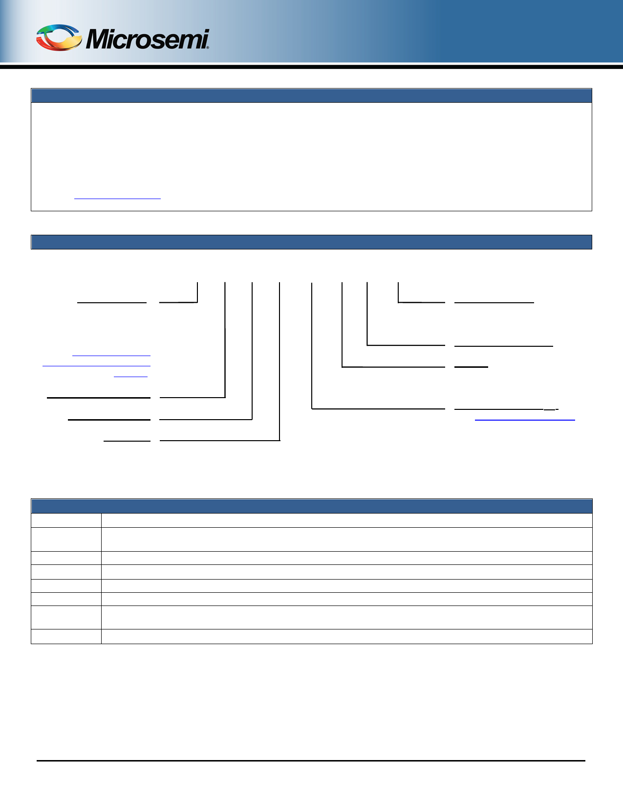
Reliability Level*
M
MA
MX
MXL
*(see High Reliability Up-
Screened Plastic Products
Portfolio)
Surface Mount Package
600 W Power Level
Lead Form
G = Gull-Wing
J = J-Bend
PART NOMENCLATURE
M SM B G 5.0 C A e3
RoHS Compliance
e3 = RoHS Compliant
Blank = non-RoHS Compliant
+/- 5% Tolerance Level
Polarity
C = bidirectional
Blank = unidirectional
Stand-Off Voltage (VWM)
(see Electrical Characteristics
table)
Symbol
VW M
PPP
V (BR)
ID
IPP
VC
IBR
SYMBOLS & DEFINITIONS
Definition
Working Peak (Standoff) Voltage - The maximum peak voltage that can be applied over the operating temperature
range. This is also referred to as standoff voltage.
Peak Pulse Power - Rated random recurring peak impulse power dissipation.
Breakdown Voltage - The minimum voltage the device will exhibit at a specified current.
Standby Current - The current at the rated standoff voltage (VWM).
Peak Pulse Current - The peak current during the impulse.
Clamping Voltage - Clamping voltage at IPP (peak pulse current) at the specified pulse conditions (typically shown as
maximum value).
Breakdown Current – The current used for measuring breakdown voltage V(BR).
RF01000, Rev. C (1/4/13)
©2013 Microsemi Corporation
Page 2 of 7
Share Link: 