ST8024L View Datasheet(PDF) - STMicroelectronics
Part Name
Description
Manufacturer
ST8024L Datasheet PDF : 35 Pages
| |||
ST8024L
3
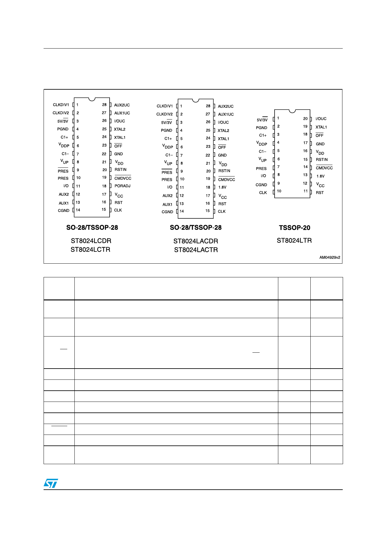
Pin configuration
Figure 2. Pin connections
Pin configuration
Table 2. Pin description
Symbol
Name and function
SO-28/
TSSOP-20
TSSOP-28
CLKDIV1
Control of CLK frequency
(internal 11 kΩ pull-up resistor connected to VDD)
1
CLKDIV2
Control of CLK frequency
(internal 11 kΩ pull-down resistor connected to GND)
2
5 V or 3 V VCC selection for communication with the smartcard. Logic high
5V/3V
selects 5 V operation and logic low selects 3 V operation (for ST8024LACDR,
ST8024LACTR, and ST8024LTR: if the 1.8V pin is logic high, the 5V/3V pin is
3
a “don't care”). See Table 23 for a description of the VCC selection settings.
PGND Power ground for step-up converter
4
C1+ External capacitor step-up converter
5
N. A.
N. A.
1
2
3
VDDP
C1–
VUP
PRES
PRES
Power supply for step-up converter
External capacitor step-up converter
Output of step-up converter
Card presence input (active low) - bonding option
Card presence input (active high)
6
4
7
5
8
6
9
N. A.
10
7
I/O
Data line to and from card (C7)
(internal 11 kΩ pull-up resistor connected to VCC)
11
8
Doc ID 17709 Rev 5
7/35
Share Link: 