UDA1351TS View Datasheet(PDF) - Philips Electronics
Part Name
Description
Manufacturer
UDA1351TS Datasheet PDF : 28 Pages
| |||
Philips Semiconductors
96 kHz IEC 958 audio DAC
Preliminary specification
UDA1351TS
8.5 Control
The UDA1351TS can be controlled by means of static pins
or via the L3 interface. For optimum use of the features of
the UDA1351TS, the L3 control mode is recommended
since only basic functions are available in the static pin
control mode.
It should be noted that the static pin control mode and
L3 control mode are mutually exclusive. In the static pin
control mode, pins L3MODE and L3DATA are used to
select the format for the data output and input interface.
8.5.1 STATIC PIN CONTROL MODE
The default values for all non-pin controlled settings are
identical to the default values at start-up in the L3 control
mode.
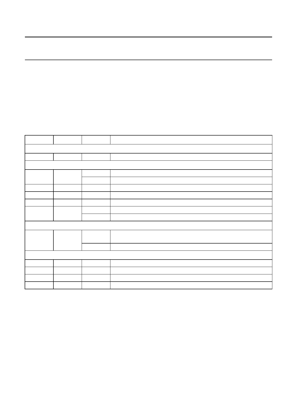
Table 3 Pin description of static pin control mode
PIN
NAME
VALUE
FUNCTION
Mode selection pin
26
SELSTATIC
1
select static pin control mode; must be connected to VDDD
Input pins
5
RESET
0
normal operation
1
reset
8
L3DATA
9
L3CLOCK
10
L3MODE
11
MUTE
0
must be connected to VSSD
0
must be connected to VSSD
0
must be connected to VSSD
0
normal operation
1
mute active
Status pin
16
LOCK
0
clock regeneration and IEC 958 decoder out-of-lock or non-PCM data
detected
1
clock regeneration and IEC 958 decoder locked and PCM data detected
Test pins
4
TEST1
18
TEST2
25
TEST4
28
TEST3
0
must be connected to digital ground (VSSD)
0
must be connected to digital ground (VSSD)
1
must be connected to digital supply voltage (VDDD)
0
must be connected to digital ground (VSSD)
2000 Mar 28
10
Share Link: 