BLV194 View Datasheet(PDF) - Philips Electronics
Part Name
Description
Manufacturer
BLV194 Datasheet PDF : 11 Pages
| |||
Philips Semiconductors
UHF power transistor
Product specification
BLV194
CHARACTERISTICS
Tj = 25 °C, unless otherwise specified.
SYMBOL
PARAMETER
CONDITIONS
V(BR)CEO
V(BR)CES
V(BR)EBO
ICER
hFE
Cc
Cre
Cc-mb
collector-emitter breakdown voltage
collector-emitter breakdown voltage
emitter-base breakdown voltage
collector leakage current
DC current gain
collector capacitance
feedback capacitance
collector-mounting base capacitance
IB = 0; IC = 40 mA
IC = 20 mA; VBE = 0
IC = 0; IE = 5 mA
RBE = 700 Ω; VCE = 16 V
IC = 1.2 A; VCE = 10 V (note 1)
IE = ie = 0; VCB = 12.5 V; f = 1 MHz
IC = 0; VCB = 12.5 V; f = 1 MHz
MIN. TYP. MAX. UNIT
16 −
−
V
32 −
−
V
3
−
−
V
−
−
1
mA
25 70 −
−
26 −
pF
−
19 −
pF
−
2
−
pF
Note
1. Measured under pulse conditions: tp ≤ 200 µs; δ ≤ 0.02.
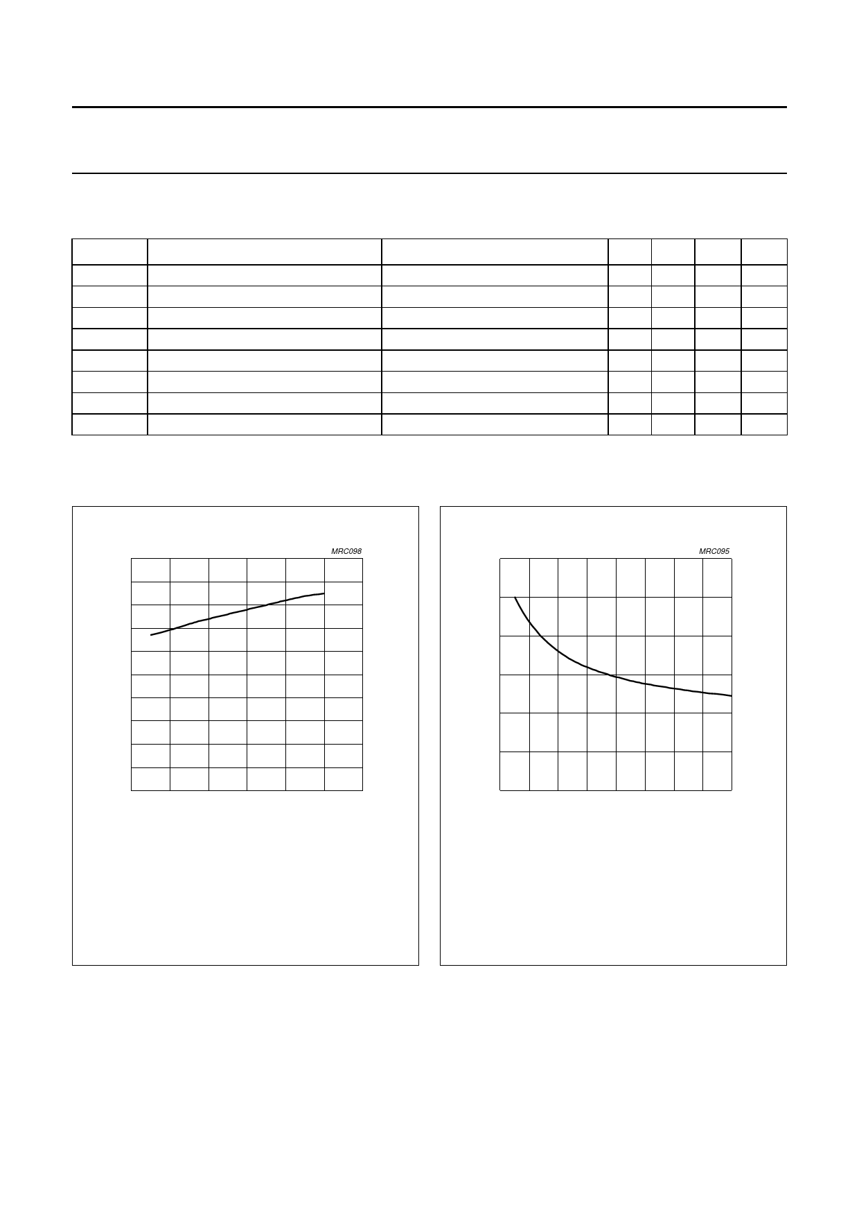
handbook1, 0ha0lfpage
hFE
80
60
40
20
0
0
2
MRC098
4
6
IC (A)
VCE = 10 V.
Measured under pulse conditions: tp ≤ 200 µs;
δ ≤ 0.02.
Fig.4 DC current gain as a function of collector
current, typical values.
handbook, 6h0alfpage
Cc
(pF)
40
MRC095
20
0
0
4
8
12
16
VCB (V)
IE = ie = 0; f = 1 MHz.
Fig.5 Collector capacitance as a function of
collector-base voltage, typical values.
January 1993
4
Share Link: 