MC33594 View Datasheet(PDF) - NXP Semiconductors.
Part Name
Description
Manufacturer
MC33594 Datasheet PDF : 28 Pages
| |||
Freescale SMeCm33ic59o4nductor, Inc.
STATE MACHINES
AFTER POR RESET STATE MACHINE
There are 3 different modes for the receiver.
Sleep mode corresponds to the low power consumption mode:
- if SOE=0, the whole receiver is shutdown,
- if SOE=1, the strobe oscillator remains active.
Configuration mode is used for writing or reading the internal registers. In this mode, the SPI is slave and the
receiver is enabled. The crystal oscillator is running and generates the clock for the SPI. This implies that before
the circuit is in sleep mode, a delay corresponding to the crystal oscillator wake-up time must be inserted
between the falling edge on RESETB and the start of the transmission on the SPI lines. The local oscillator is
running as well. This means that demodulated data can be read on DMDAT but are not sent by the SPI.
In Run mode, the receiver is enabled (crystal and local oscillators are running). It is either waiting for an RF
telegram or receiving one.
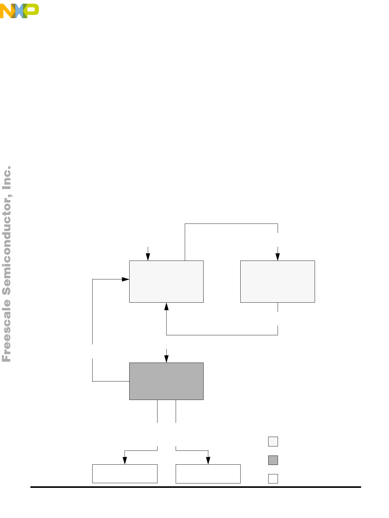
Figure 14 details the state machine after Power On Reset (POR). The state machine is synchronized by a
sampling clock at 615kHz (sampling period Ts=1.6µs), derivated from the crystal oscillator. The transition time
between state 1 and states 2 or 6 is less than 3 × Ts.
After POR, the circuit is in state 0 and configuration registers’ content is set to the reset value. This enables to
use ROMEO2 in a standalone configuration without any external control.
As long as a low level is applied on RESETB, the circuit stays in state 1. This configuration mode enables to write
or read the internal registers through the SPI interface.
Figure 14: After POR state machine
Power-On Reset
Strobe Counter=SR
OR STROBE=1
State 0
Sleep mode
SPI disabled
RESETB=1
AND DME=0
RESETB=0
State 1
Configuration mode
SPI active and slave
State 0b
Run mode
Raw data on MOSI
SPI disabled
Strobe Counter ≠ SR
AND STROBE=0
© Motorola, Inc., 2002.
RESETB=1
AND DME=1
AND SOE=1
RESETB=1
AND DME=1
AND SOE=0
State 2, see figure 15
State 6, see figure 16
FMorOTMOoRrOeLIAnSfoErMmICaOtNioDnUCOTnORTShPisROPDroUdCuTSct,
Go to: www13.freescale.com
SPI disabled
SPI slave
SPI master
revision 1.1, 5 February 2002
Share Link: 