BD8158FVM(2010) Ver la hoja de datos (PDF) - ROHM Semiconductor
Número de pieza
componentes Descripción
Fabricante
BD8158FVM
(Rev.:2010)
(Rev.:2010)
ROHM Semiconductor
BD8158FVM Datasheet PDF : 18 Pages
| |||
BD8152FVM, BD8158FVM
Technical Note
Selecting Application Components
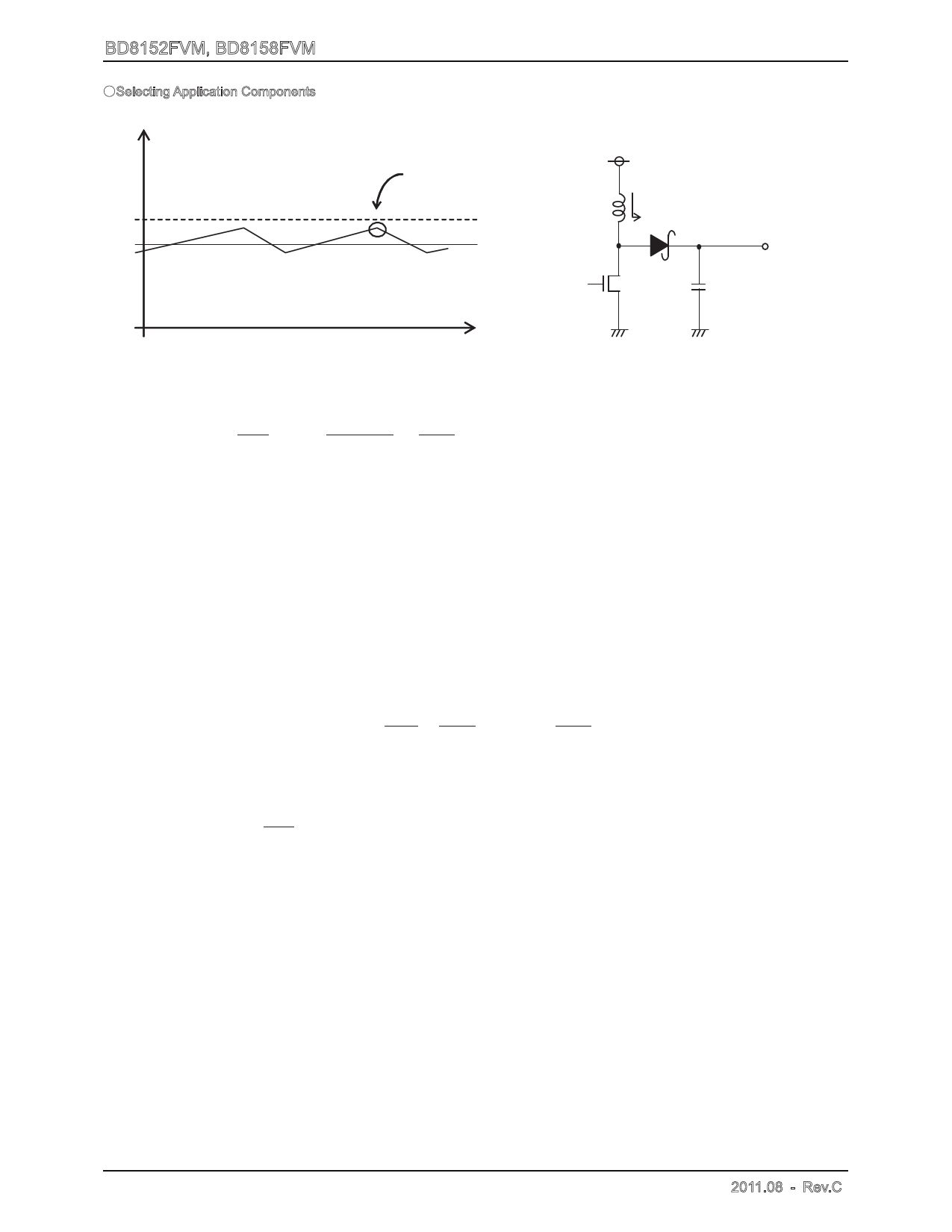
(1) Setting the output L constant
The coil L to use for output is decided by the rating current ILR and input current maximum value IINMAX of the coil.
IL
IINMAX + IL should not
VCC
reach the rating value level
L
IL
ILR
IINMAX average
Vo
current
Co
t
Fig. 23 Coil current waveform
Fig. 24 Output Application Circuit Diagram
Adjust so that IINMAX + ∆IL does not reach the rating current value ILR. At this time, ∆IL can be obtained by the following
equation.
1
Vo - Vcc
1
∆IL= L Vcc
Vo
f
[A] Where, f is the switching frequency.
Set with sufficient margin because the coil L value may have the dispersion of approx. 30%. If the coil current exceeds
the rating current ILR of the coil, it may damage the IC internal element.
BD8152FVM,BD8158FVM use the current mode DC/DC converter control and has the optimized design at the coil value.
The following coil values are recommended from the aspects of power efficiency, response and safety. When the coil out
of this range is selected, the stable continual operation is not guaranteed such as the switching waveform becomes
irregular. Please pay attention to it.
Switching frequency: L = 10 uH to 22 uH at 600 kHz
Switching frequency: L = 4.7 uH to 15 uH at 1,200 kHz
(2) Setting the output capacitor
For the capacitor C to use for the output, select the capacitor which has the larger value in the ripple voltage VPP
allowance value and the drop voltage allowance value at the time of sudden load change. Output ripple voltage is
decided by the following equation.
∆VPP
= ILMAX RESR + 1 Vcc (ILMAX -
fCo
Vo
∆IL )
2
[V] Where, f is the switching frequency.
Perform setting so that the voltage is within the allowable ripple voltage range.
For the drop voltage during sudden load change; VDR, please perform the rough calculation by the following equation.
VDR = ∆I
Co
10u sec
[V]
However, 10 s is the rough calculation value of the DC/DC response speed. Please set the capacitance considering the
sufficient margin so that these two values are within the standard value range.
(3) Selecting the input capacitor
Since the peak current flows between the input and output at the DC/DC converter, a capacitor is required to install at the
input side. For this reason, the low ESR capacitor is recommended as an input capacitor which has the value more than
10μF and less than 100 mΩ. If a capacitor out of this range is selected, the excessive ripple voltage is superposed on the
input voltage, accordingly it may cause the malfunction of IC.
However these conditions may vary according to the load current, input voltage, output voltage, inductance and switching
frequency. Be sure to perform the margin check using the actual product.
www.rohm.com
© 2010 ROHM Co., Ltd. All rights reserved.
8/17
2010.03 - Rev.B
Share Link: 