M5M417400CJ-7 Ver la hoja de datos (PDF) - MITSUBISHI ELECTRIC
Número de pieza
componentes Descripción
Fabricante
M5M417400CJ-7 Datasheet PDF : 22 Pages
| |||
MITSUBISHI LSIs
M5M417400CJ,TP-5,-6,-7,-5S,-6S,-7S
FAST PAGE MODE 16777216-BIT (4194304-WORD BY 4-BIT) DYNAMIC RAM
TEST Mode SET Cycle
Symbol
Parameter
tWSR
tWHR
W setup time before RAS low
W hold time after RAS low
Limits
M5M417400C-5,-5S
M5M417400C-6,-6S
M5M417400C-7,-7S
Unit
Min
Max
Min
Max
Min
Max
10
10
10
ns
10
10
15
ns
Note 27:
The test mode function is initiated by a W and CAS before RAS cycle (WCBR cycle) as specified in timing diagram.
The test mode function is terminated by either a CAS before RAS refresh cycle (CBR refresh cycle) or a RAS only refresh cycle.
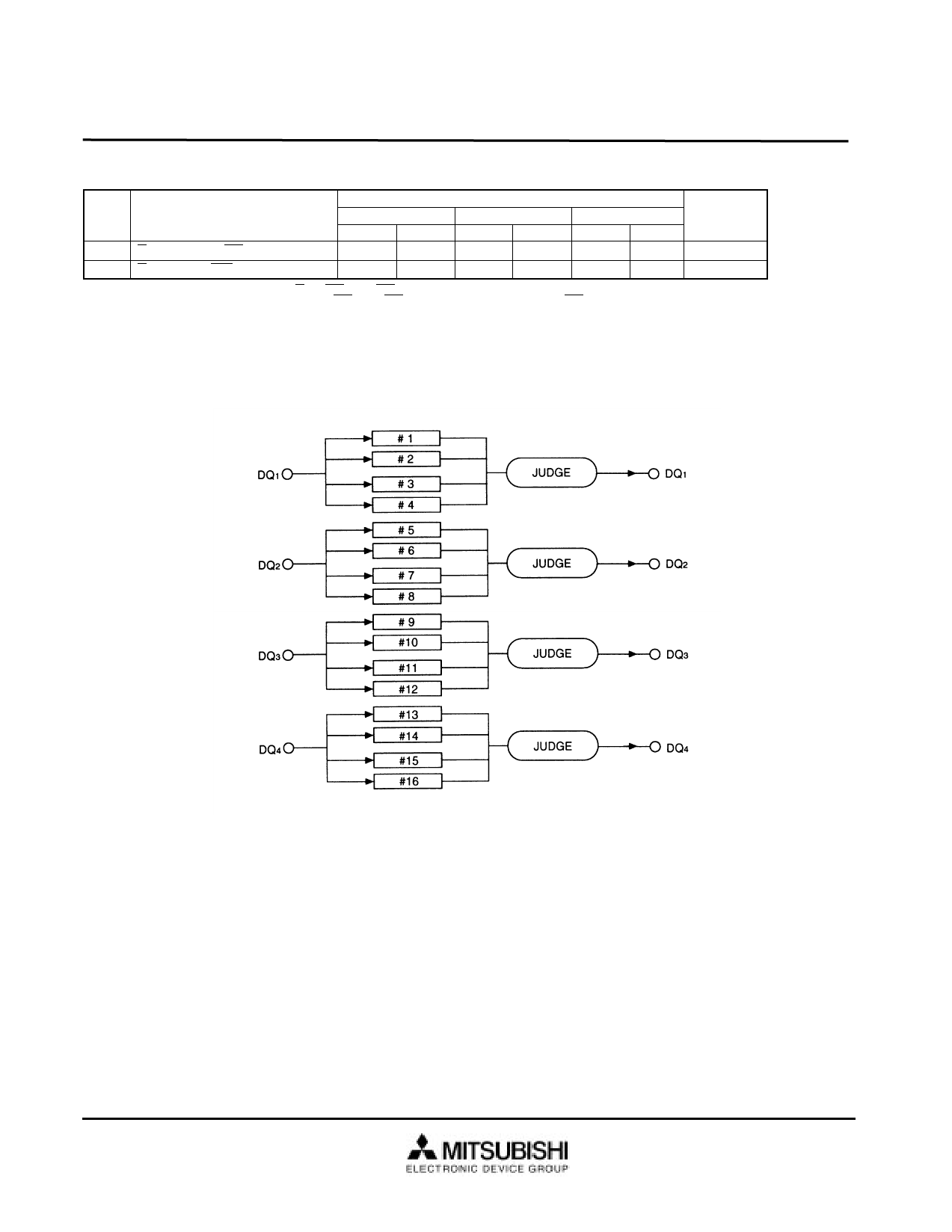
During the test mode, the device is internally organized as 16-bits wide (1M bytes depth). No addressing of CA0 and CA1 is required.
During a write cycle, data must be applied to all DQ (input) pins. The data can be different between DQ pins. The data on each DQ pin is written into 4-bits memory cells,
respectively. During a read cycle, each DQ (output) pin shows the test result of the 4-bits, respectively. High state indicates that they are same. Low state indicates that they
are not same.
During the test mode operation, only WCBR cycle can be used to perform refresh.
9
Share Link: 