ADXL313WACPZ Ver la hoja de datos (PDF) - Analog Devices
Número de pieza
componentes Descripción
Fabricante
ADXL313WACPZ Datasheet PDF : 28 Pages
| |||
Data Sheet
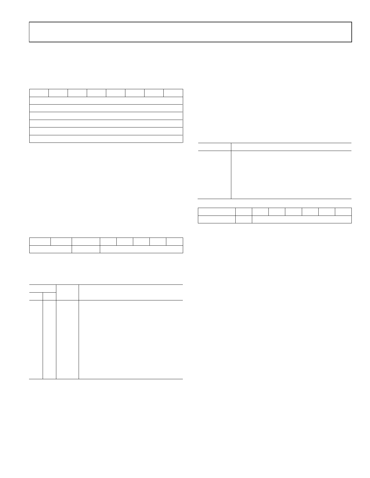
Register 0x32 and Register 0x33—DATA_X0, DATA_X1
(Read Only),
Register 0x34 and Register 0x35—DATA_Y0, DATA_Y1
(Read Only),
Register 0x36 and Register 0x37—DATA_Z0, DATA_Z1
(Read Only)
D7 D6 D5 D4 D3 D2 D1 D0
DATA_X0[7:0]
DATA_X1[7:0]
DATA_Y0[7:0]
DATA_Y1[7:0]
DATA_Z0[7:0]
DATA_Z1[7:0]
These six bytes (Register 0x32 to Register 0x37) are eight bits
each and hold the output data for each axis. Register 0x32 and
Register 0x33 hold the output data for the x-axis, Register 0x34 and
Register 0x35 hold the output data for the y-axis, and Register 0x36
and Register 0x37 hold the output data for the z-axis.
The output data is twos complement, with DATA_x0 as the least
significant byte and DATA_x1 as the most significant byte, where x
represent X, Y, or Z. The DATA_FORMAT register (Address 0x31)
controls the format of the data. It is recommended that a multiple-
byte read of all registers be performed to prevent a change in
data between reads of sequential registers.
Register 0x38—FIFO_CTL (Read/Write)
D7
D6
D5
D4 D3 D2 D1 D0
FIFO_MODE
Trigger
Samples
FIFO_MODE Bits
These bits set the FIFO mode, as described in Table 17.
Table 17. FIFO Modes
Setting
D7 D6 Mode Function
0 0 Bypass FIFO is bypassed.
0 1 FIFO
FIFO collects up to 32 values and then
stops collecting data, collecting new data
only when FIFO is not full.
1 0 Stream FIFO holds the last 32 data values. When
FIFO is full, the oldest data is overwritten
with newer data.
1 1 Trigger When triggered by the trigger bit, FIFO
holds the last data samples before the
trigger event and then continues to collect
data until full. New data is collected only
when FIFO is not full.
ADXL313
Trigger Bit
A value of 0 in the trigger bit links the trigger event to INT1,
and a value of 1 links the trigger event to INT2.
Samples Bits
The function of these bits depends on the FIFO mode selected
(see Table 18). Entering a value of 0 in the samples bits immedi-
ately sets the watermark status bit in the INT_SOURCE register,
regardless of which FIFO mode is selected. Undesirable opera-
tion may occur if a value of 0 is used for the samples bits when
trigger mode is used.
Table 18. Samples Bits Functions
FIFO Mode Samples Bits Function
Bypass
None.
FIFO
Specifies how many FIFO entries are needed to
trigger a watermark interrupt.
Stream
Specifies how many FIFO entries are needed to
trigger a watermark interrupt.
Trigger
Specifies how many FIFO samples are retained in
the FIFO buffer before a trigger event.
0x39—FIFO_STATUS (Read Only)
D7
D6 D5 D4 D3 D2 D1 D0
FIFO_TRIG 0
Entries
FIFO_TRIG Bit
A 1 in the FIFO_TRIG bit corresponds to a trigger event occurring,
and a 0 means that a FIFO trigger event has not occurred.
Entries Bits
These bits report how many data values are stored in the FIFO.
Access to collect the data from the FIFO is provided through
the DATA_Xx, DATA_Yx, and DATA_Zx registers. FIFO reads
must be done in burst or multiple-byte mode because each FIFO
level is cleared after any read (single- or multiple-byte) of the
FIFO. The FIFO stores a maximum of 32 entries, which equates
to a maximum of 33 entries available at any given time because
an additional entry is available at the output filter of the device.
Rev. 0 | Page 21 of 28
Share Link: 