MU9C8338-TFI Ver la hoja de datos (PDF) - Music Semiconductors
Número de pieza
componentes Descripción
Fabricante
MU9C8338-TFI Datasheet PDF : 28 Pages
| |||
Functional Description
MU9C8338 10/100Mb Ethernet Filter Interface
MAC Address Storage
When the MU9C8338 performs an SA processing
function, it automatically extracts the MAC address from
the packet. The database is searched and the MAC address
is added to the LANCAM database if necessary. Similarly,
when a DA processing function is performed, the
MU9C8338 automatically searches the database for the
extracted DA MAC address.
It is important that the user is aware of the byte ordering of
the 48-bit MAC address when it is stored in the LANCAM
database. This is because the user must byte-order MAC
addresses identically when a database entry is to be
manually added or deleted. Similarly, if the user wishes to
read out a MAC address, they should also be aware of the
byte ordering when the relevant data registers are read.
Throughout this data sheet MAC addresses are shown as
bit 47 being the most significant bit, which is placed on the
left. Similarly, bit 0 is shown as the least significant bit and
placed on the right. Using this notation, the
Individual/Group (I/G) bit subfield would be shown as bit
40. This bit would be the first bit of an address transmitted
onto the serial network and also the first bit received. The
IEEE 802.3 refers to the I/G bit subfield as bit 0. If the bit
is set to 1, it indicates that the address is a group address.
Conversely, if the bit is set to 0, it indicates it is an
individual address. Figure 4 shows a typical 48-bit MAC
address used in Ethernet or IEEE 802.3 networks.
MAC Address
47
40 39
32 31
24 23
16 15
08 07
00
02
:
60
:
8C
:
12
:
34
:
56
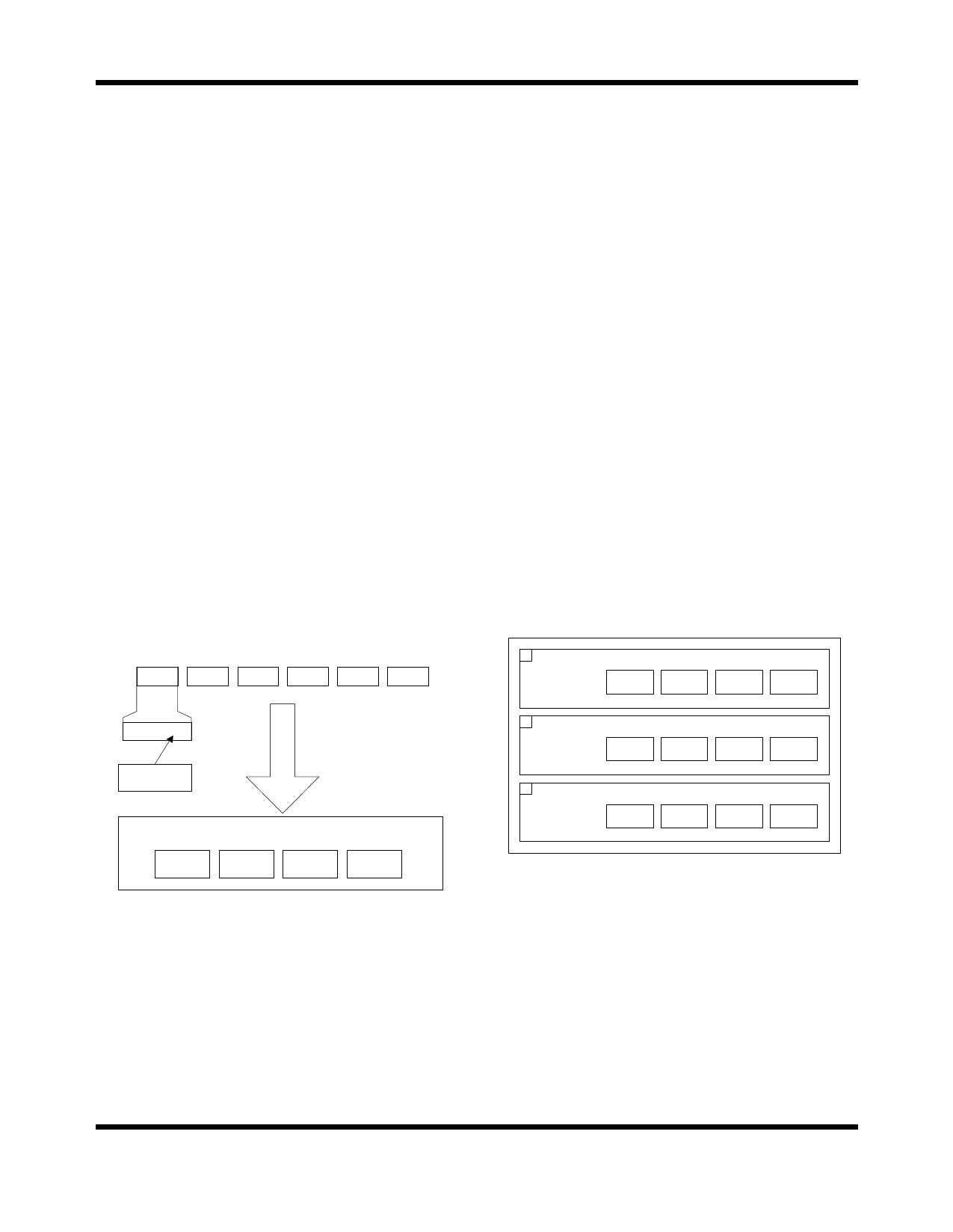
If the MAC address shown in Figure 4 is added to the
database by the MU9C8338, it is stored as follows:
• Segment 3 = 6002h
• Segment 2 = 128Ch
• Segment 1 = 5634h
• Segment 0 = Associated data (permanent bit, time
stamp and port ID)
If the user wishes to use the built-in routines to manually
add, delete, or read MAC addresses from the database, the
System CAM Word registers (SCDW) are used as shown
in Figure 5. It shows how the MAC address, used as an
example in Figure 4, would be transferred using the
SCDW registers.
If the user intended to delete the MAC address, the SCDW
registers would be written as shown in item 1 and the
SDO_DELETE routine would be invoked.
If the user intended to add the address manually, the
SCDW registers would be written as shown in item 2 and
the SDO_ADD routine would be invoked.
Finally, if the user intended to read an entry, the
SDO_READ routine would be invoked and the address
would be read from the SCDW registers as shown in item
3. The built-in routines are explained more fully later in
this document.
1
SDO_DELETE
SCDW3
not used
SCDW2
6002
SCDW1
128C
SCDW0
5634
0000 0010
IEEE bit 0
I/G bit
seg 3
6002
LANCAM Database Entry
seg 2
seg 1
128C
5634
seg 0
assoc. data
Figure 4: MAC Address Byte Order
2
SDO_ADD
3
SDO_READ
SCDW3
6002
SCDW2
128C
SCDW1
5634
SCDW0
assoc. data
SCDW3
6002
SCDW2
128C
SCDW1
5634
SCDW0
assoc. data
Figure 5: SCDW Register Order
Rev. 1a
9
Share Link: 