CLC1004 Ver la hoja de datos (PDF) - Cadeka Microcircuits LLC.
Número de pieza
componentes Descripción
Fabricante
CLC1004 Datasheet PDF : 20 Pages
| |||
Data Sheet
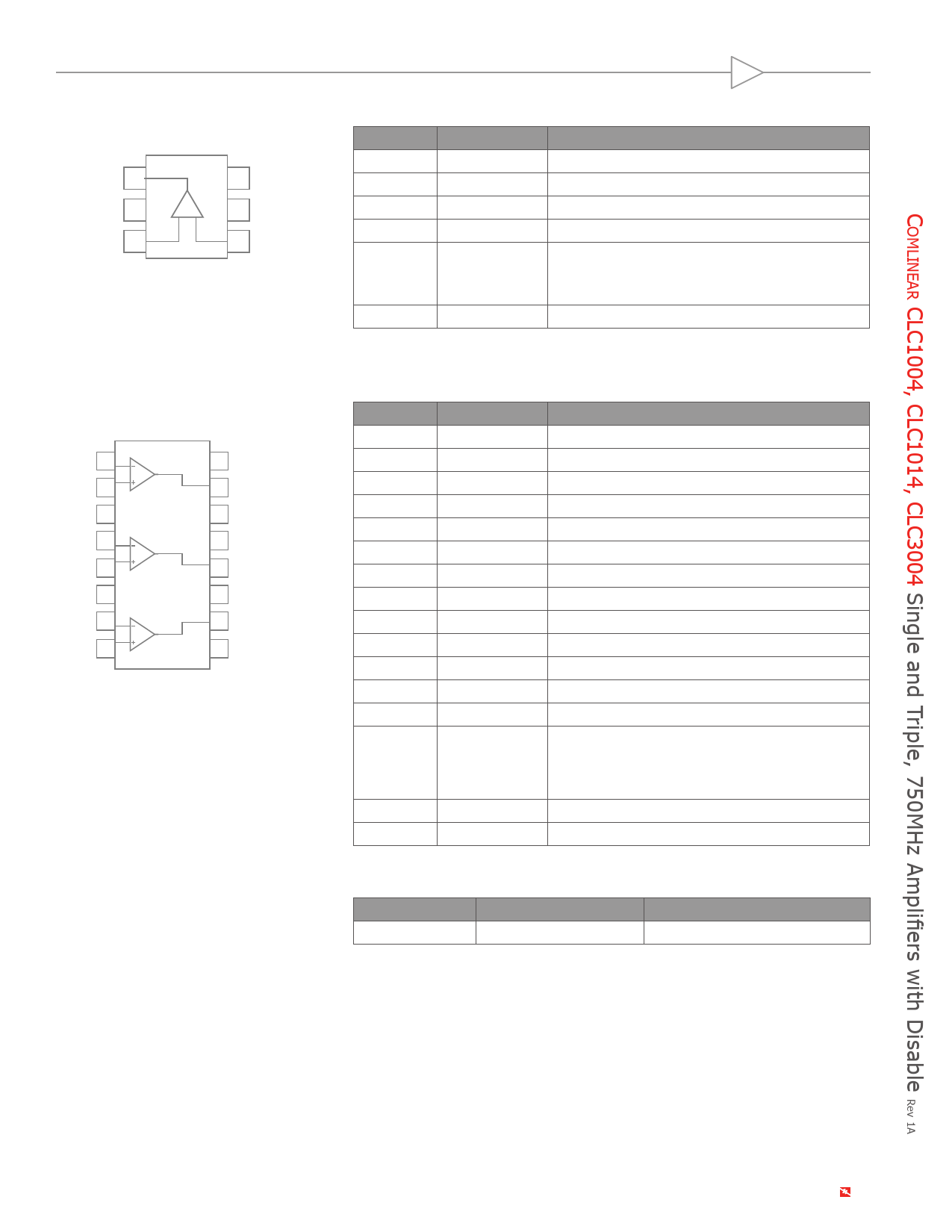
CLC1004 Pin Configuration
OUT 1
6 +VS
-VS 2
+-
5 DIS
+IN 3
4 -IN
CLC3004 Pin Configuration
-IN1 1
+IN1 2
-VS 3
-IN2 4
+IN2 5
-VS 6
-IN3 7
+IN3 8
16 +VS
15 OUT1
14 DIS
13 +VS
12 OUT2
11 +VS
10 OUT3
9 -VS
CLC1004 Pin Assignments
Pin No.
1
2
3
4
5
6
Pin Name
OUT
-VS
+IN
-IN
DIS
+VS
Description
Output
Negative supply
Positive input
Negative input
Disable pin. Enabled if pin is grounded, left float-
ing or pulled below VON, disabled if pin is pulled
above VOFF.
Positive supply
CLC3004 Pin Configuration
Pin No.
1
2
3
4
5
6
7
8
9
10
11
12
13
Pin Name
-IN1
+IN1
-VS
-IN2
+IN2
-VS
-IN3
+IN3
-VS
OUT3
+VS
OUT2
+VS
Description
Negative input, channel 1
Positive input, channel 1
Negative supply
Negative input, channel 2
Positive input, channel 2
Negative supply
Negative input, channel 3
Positive input, channel 3
Negative supply
Output, channel 3
Positive supply
Output, channel 2
Positive supply
Disable pin. Enabled if pin is grounded, left float-
14
DIS
ing or pulled below VON, disabled if pin is pulled
above VOFF.
15
OUT1
Output, channel 1
16
+VS
Positive supply
Disable Pin Truth Table
Pin
High
DIS
Disabled
Low*
Enabled
*Default Open State
©2007-2008 CADEKA Microcircuits LLC
www.cadeka.com 2
Share Link: 