L6566B Ver la hoja de datos (PDF) - STMicroelectronics
Número de pieza
componentes Descripción
Fabricante
L6566B Datasheet PDF : 51 Pages
| |||
L6566B
Application information
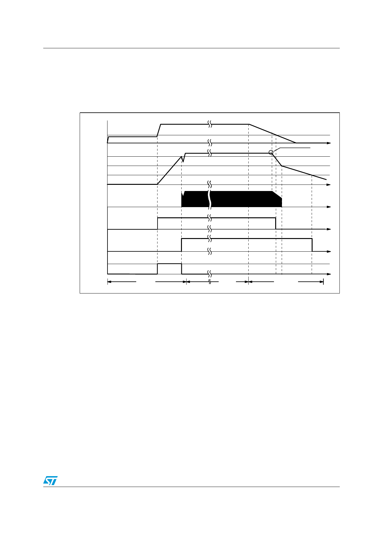
With reference to the timing diagram of Figure 6, when power is first applied to the converter
the voltage on the bulk capacitor (Vin) builds up and, at about 80 V, the HV generator is
enabled to operate (HV_EN is pulled high) so that it draws about 1 mA. This current, minus
the device’s consumption, charges the bypass capacitor connected from pin Vcc (5) to
ground and makes its voltage rise almost linearly.
Figure 6. Timing diagram: normal power-up and power-down sequences
Vin
VHVstart
Vcc
(pin 5)
VccON
VccOFF
Vccrestart
regulation is lost here
t
t
GD
(pin 4)
t
HV_EN
Vcc_OK
t
Icharge
t
0.85 mA
Power-on
Normal
operation
Power-off
t
As the Vcc voltage reaches the turn-on threshold (14 V typ.) the device starts operating and
the HV generator is cut off by the Vcc_OK signal asserted high. The device is powered by
the energy stored in the Vcc capacitor until the self-supply circuit (typically an auxiliary
winding of the transformer and a steering diode) develops a voltage high enough to sustain
the operation. The residual consumption of this circuit is just the one on the 15 MΩ resistor
(≈10 mW at 400 Vdc), typically 50-70 times lower, under the same conditions, as compared
to a standard start-up circuit made with external dropping resistors.
At converter power-down the system will lose regulation as soon as the input voltage is so
low that either peak current or maximum duty cycle limitation is tripped. Vcc will then drop
and stop IC activity as it falls below the UVLO threshold (10 V typ.). The Vcc_OK signal is
de-asserted as the Vcc voltage goes below a threshold VCCrest located at about 5V. The HV
generator can now restart. However, if Vin < Vinstart, as illustrated in Figure 6, HV_EN is de-
asserted too and the HV generator is disabled. This prevents converter’s restart attempts
and ensures monotonic output voltage decay at power-down in systems where brownout
protection (see the relevant section) is not used.
The low restart threshold VCCrest ensures that, during short circuits, the restart attempts of
the device will have a very low repetition rate, as shown in the timing diagram of Figure 7 on
page 20, and that the converter will work safely with extremely low power throughput.
19/51
Share Link: 