LB11985H Ver la hoja de datos (PDF) - SANYO -> Panasonic
Número de pieza
componentes Descripción
Fabricante
LB11985H Datasheet PDF : 9 Pages
| |||
Truth Table and Control Functions
Source → Sink
V→W
1
W →V
U→W
2
W→U
U→V
3
V→U
W →V
4
V→W
W→U
5
U→W
V→U
6
U→V
Hall input
FR
U
V
W
H
H
H
L
L
H
H
L
L
L
H
H
L
H
L
H
L
L
H
L
H
L
H
H
L
H
L
H
L
L
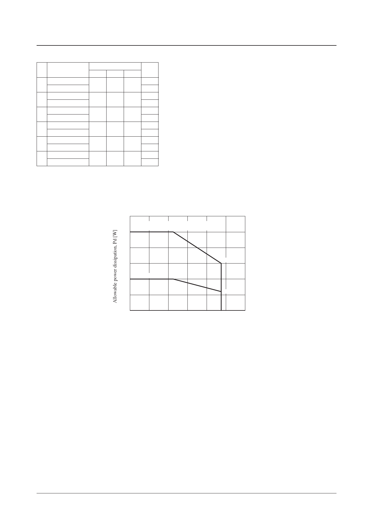
Allowable Power Dissipation
LB11985H
Note: 1. In the FR column, “H” indicates a voltage of 2.75 V or higher, and “L”
indicates a voltage of 2.25 V or lower. (When VCC is 5 V.)
2. For the Hall inputs, the input high state is defined to be the state where
the (+) input is higher than the corresponding (–) input by at least 0.02 V,
and the input low state is defined to be the state where the (+) input is
lower than the corresponding (–) input by at least 0.02 V.
Pd max — Ta
2.4
Mounted on the specified printed circuit board
(76.1 × 114.3 × 1.6 mm3 glass epoxy board)
2.0
1.6
1.20
1.2
Independent IC
0.8
0.48
0.4
0
–20
0
20
40
60
80
100
Ambient temperature, Ta [°C]
No. 6209-3/9
Share Link: 