LTC4075EDD Ver la hoja de datos (PDF) - Linear Technology
Número de pieza
componentes Descripción
Fabricante
LTC4075EDD Datasheet PDF : 16 Pages
| |||
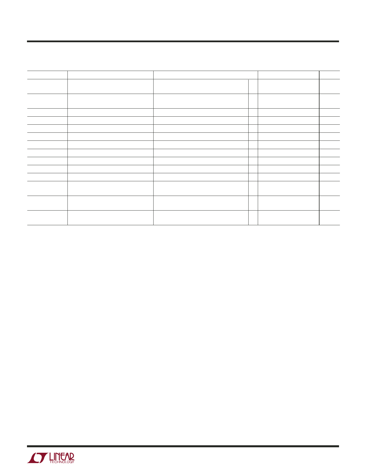
LTC4075/LTC4075X
ELECTRICAL CHARACTERISTICS The ● denotes the specifications which apply over the full operating
temperature range, otherwise specifications are at TA = 25°C. VDCIN = 5V, VUSBIN = 5V unless otherwise noted.
SYMBOL
VASD-DC
VASD-USB
VENABLE
RENABLE
V⎯C⎯H⎯R⎯G
V⎯P⎯W⎯R
VUSBPWR
ΔVRECHRG
tRECHRG
tTERMINATE
tSS
RON-DC
RON-USB
TLIM
PARAMETER
VDCIN – VBAT Lockout Threshold
VUSBIN – VBAT Lockout Threshold
ENABLE Input Threshold Voltage
ENABLE Pulldown Resistance
⎯C⎯H⎯R⎯G Output Low Voltage
⎯P⎯W⎯R Output Low Voltage
USBPWR Output Low Voltage
Recharge Battery Threshold
Recharge Comparator Filter Time
Termination Comparator Filter Time
Soft-Start Time
Power FET “ON” Resistance
(Between DCIN and BAT)
Power FET “ON” Resistance
(Between USBIN and BAT)
Junction Temperature in
Constant-Temperature Mode
CONDITIONS
VDCIN from Low to High, VBAT = 4.2V
VDCIN from High to Low, VBAT = 4.2V
VUSBIN from Low to High
VUSBIN from High to Low
I⎯C⎯H⎯R⎯G = 5mA
I⎯P⎯W⎯R = 5mA
IUSBPWR = 300µA
VFLOAT – VRECHRG, 0°C < TA < 85°C
VBAT from High to Low
IBAT Drops Below Termination Threshold
IBAT = 0 to Full-Scale
MIN TYP MAX UNITS
140
180
220
mV
20
50
80
mV
140
180
220
mV
20
50
80
mV
0.4
0.7
1
V
● 1.2
2
5
MΩ
0.35
0.6
V
0.35
0.6
V
0.35
0.6
V
65
100
135
mV
3
6
9
ms
0.8
1.5
2.2
ms
175
250
325
µs
400
mΩ
550
mΩ
105
°C
Note 1: Absolute Maximum Ratings are those values beyond which the life
of a device may be impaired.
Note 2: The LTC4075E/LTC4075XE are guaranteed to meet the
performance specifications from 0°C to 70°C. Specifications over the
–40°C to 85°C operating temperature range are assured by design,
characterization and correlation with statistical process controls.
Note 3: Failure to correctly solder the exposed backside of the package to
the PC board will result in a thermal resistance much higher than 40°C/W.
See Thermal Considerations.
Note 4: Supply current includes IDC and ITERM pin current (approximately
100µA each) but does not include any current delivered to the battery
through the BAT pin.
Note 5: Supply current includes IUSB and ITERM pin current
(approximately 100µA each) but does not include any current delivered to
the battery through the BAT pin.
Note 6: This parameter is not applicable to the LTC4075X.
Note 7: Guaranteed by long term current density limitations.
4075Xf
3
Share Link: 