SSM2161 Ver la hoja de datos (PDF) - Analog Devices
Número de pieza
componentes Descripción
Fabricante
SSM2161 Datasheet PDF : 16 Pages
| |||
SSM2160/SSM2161
Controlling Stereo Headphones Level and Balance
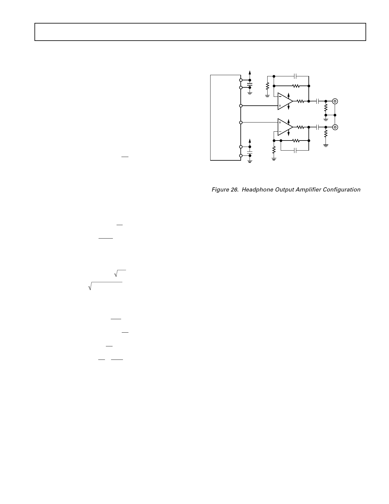
Figure 26 shows how the SSM2160 can be configured to drive a
stereo headphone output amplifier. Note that the minimum
load specification precludes driving headphones directly. This
example assumes that audio left and right signals are being fed
into Channels 1 and 2, respectively. Additional amplifiers could
be connected to the outputs to provide additional channels.
The master control will set the loudness, and the channel
controls will set the balance. The headphone amplifiers may be
connected to the same power supplies as the SSM2160. The
stereo audio signals are directly coupled to the noninverting
input of both op amps. Depending upon the headphones and
the signal levels, the optional R1 may be selected to provide
additional gain. The gain is determined by:
AV
=
1+
R2
R1
CAUTION: As with all headphone applications, listening to
loud sounds can cause permanent hearing loss.
+5V
V+ 1
AGND 2
+ R1*
500Ω
4
CH1OUT
SSM2160
21
CH2OUT
SSM2135-A
SSM2135-B
–5V
V– 12
+
DGND 13
R1*
500Ω
C2 100pF
R2 6kΩ
+5V
150Ω
– 5V
+5V
150Ω
15µF*
50kΩ
15µF*
– 5V
R2 6kΩ
50kΩ
C2 100pF
LEFT
HEADPHONE
600Ω
RIGHT
HEADPHONE
600Ω
As an example, suppose a high impedance headphone (600 Ω)
required a minimum of 25 mW to produce the desired loudness.
*SEE TEXT FOR ALTERNATE VALUES
Further, suppose the system design made available an output
level from the SSM2160 of 300 mV. If the output were buffered
Figure 26. Headphone Output Amplifier Configuration
without gain and applied directly to the headphone, the power
would be:
EVALUATION BOARD FOR THE SSM2160
The following information is to be used with the SSM2160
P =V 2
R
P = (0.3)2 = 0.15 mW
600
evaluation board, which simplifies connecting the part into
existing systems. Audio signals are fed in and out via standard
RCA-type audio connectors. A stereo headphone driver socket
is provided for the convenience of listening to Channels 1 and
2. Microsoft Windows software is available for controlling the
This is obviously too little power, so we solve the equation for
serial data bus of the SSM2160 via the parallel port driver
the voltage required to produce the desired power of 25 mW:
(LPT) of an IBM-compatible PC. The software may be
downloaded from the Analog Devices Internet web site at
V = PR
V = 0.025 × 600 = 3.9 V rms
http://WWW.ANALOG.COM, or by requesting a diskette from
Analog Audio marketing by faxing (408)727-1550. The demo
board comes complete with the necessary parallel port cable and
The gain of the amplifiers must then be:
telephone type plug that mates with the evaluation board.
Power Supplies
AV
= 3.89 = 13
0. 3
AV
= 1+ R2
R1
R2 = 12
R1
R1 = R2 = 6000 = 500 Ω
12 12
If lower impedance headphones were used, say 30 Ω, the voltage
The demo board should be connected to ± 6 V supplies for
initial evaluation. If other supply voltages are planned, they can
be subsequently changed. The power configuration on the
evaluation board is per Figure 14.
Signal Inputs and Outputs
Input load impedances are approximately 10 kΩ, so the load on
the sources is relatively light. DC blocking capacitors are
provided on the evaluation board. The load impedance
connected to the outputs must be no less than 10 kΩ and no
more than 50 pF shunt capacitance. This enables driving short
required would be 0.9 V rms, so a gain of 3 would suffice, thus
R1 = 2.5 kΩ and R2 = 5 kΩ.
The 100 pF capacitor, C2, in parallel with R2, creates a low-
pass filter with a cutoff above the audible range, reducing the
lengths of shielded or twisted wire cable. If heavier loads must
be driven, use an external buffer as shown in Figure 25. Note
that 50 Ω isolation resistors are placed in series with each
SSM2160 output and may be jumpered if desired.
gain to high frequency noise. A small resistor within the
Digital Interface
feedback loop protects the output stage in the event of a short
The interconnecting cable provided has a DB25 male connector
circuit at the headphone output but does not measurably reduce for the parallel port of the PC and an RJ14 plug that connects to
the signal swing or loop gain. The dc blocking capacitor at the the evaluation board. This cable is all that is required for the
output establishes a high pass filter with a –3 dB corner fre-
computer interface.
quency determined by the value of C1 and the headphone
impedance. With 600 Ω headphones, an output capacitor of 15
µF sets this corner at 20 Hz. Similarly, a 30 Ω headphone will
require 250 µF.
Software Installation
If installing the software from a diskette, and using Windows
version 3.1 or later, select the RUN command from the FILE
menu of the Program Manager. In the command line, type
a:\setup and press return. If you downloaded the software to
REV. 0
–13–
Share Link: 