SG6742 Ver la hoja de datos (PDF) - Fairchild Semiconductor
Número de pieza
componentes Descripción
Fabricante
SG6742 Datasheet PDF : 14 Pages
| |||
Highly Integrated Green-Mode PWM Controller
MARKING INFORMATION
SG6742TP
XXXXXXXXYWWV
T: D = DIP, S = SOP
P: Z =Lead Free
Null=regular package
XXXXXXXX: Wafer Lot
Y: Year; WW: Week
V: Assembly Location
Product Specification
SG6742
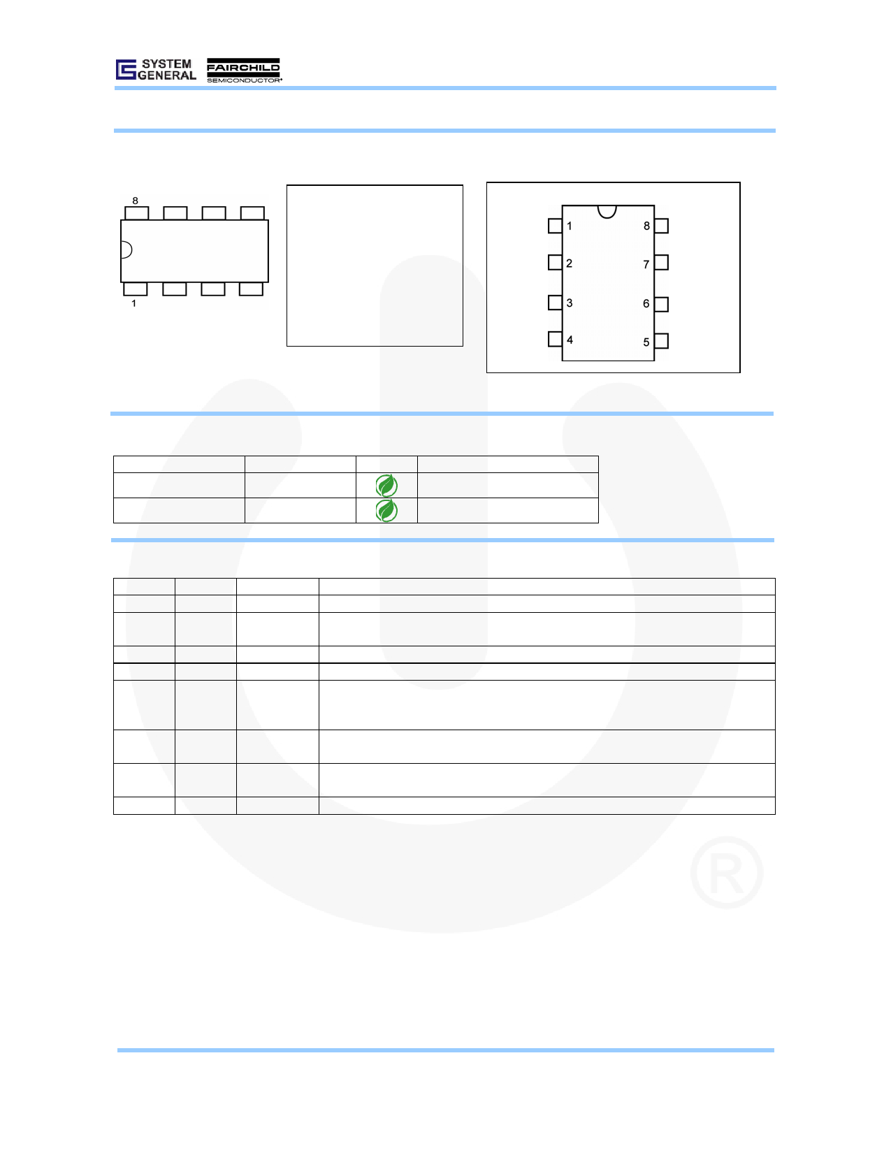
PIN CONFIGURATION
GND
FB
NC
HV
GATE
VDD
SENSE
RT
ORDERING INFORMATION
Part Number
PWM Frequency Pb-Free Package
SG6742SZ
65KHz
SOP-8
SG6742DZ (Preliminary) 65KHz
DIP-8
PIN DESCRIPTIONS
Pin No. Symbol Function
1
GND
Ground
2
FB
Feedback
3
NC
NA
4
HV
Start-up Input
Temperature
5
RT
Detection
6
SENSE Current Sense
7
VDD
Power Supply
8
GATE
Driver Output
Description
Ground.
The signal from the external compensation circuit is fed into this pin. The PWM duty cycle is
determined in response to the signal on this pin and the current-sense signal on SENSE pin.
NC pin.
For start-up, this pin is pulled high to the line input or bulk capacitor via resistors.
For over-temperature protection, an external NTC thermistor is connected from this pin to GND
pin. The impedance of the NTC decreases at high temperatures. Once the voltage of the RT
pin drops below a fixed limit, PWM output is disabled.
Current sense. The sensed voltage is used for peak-current-mode control and cycle-by-cycle
current limiting.
Power supply. The internal protection circuit disables PWM output as long as VDD exceeds the
OVP trigger point.
The totem-pole output driver. Soft driving waveform is implemented for improved EMI.
© System General Corp.
Version 1.0.1 (IAO33.0083.B0)
-2-
www.sg.com.tw • www.fairchildsemi.com
September 24, 2007
Share Link: 