TK14551V Ver la hoja de datos (PDF) - Toko America Inc
Número de pieza
componentes Descripción
Fabricante
TK14551V Datasheet PDF : 32 Pages
| |||
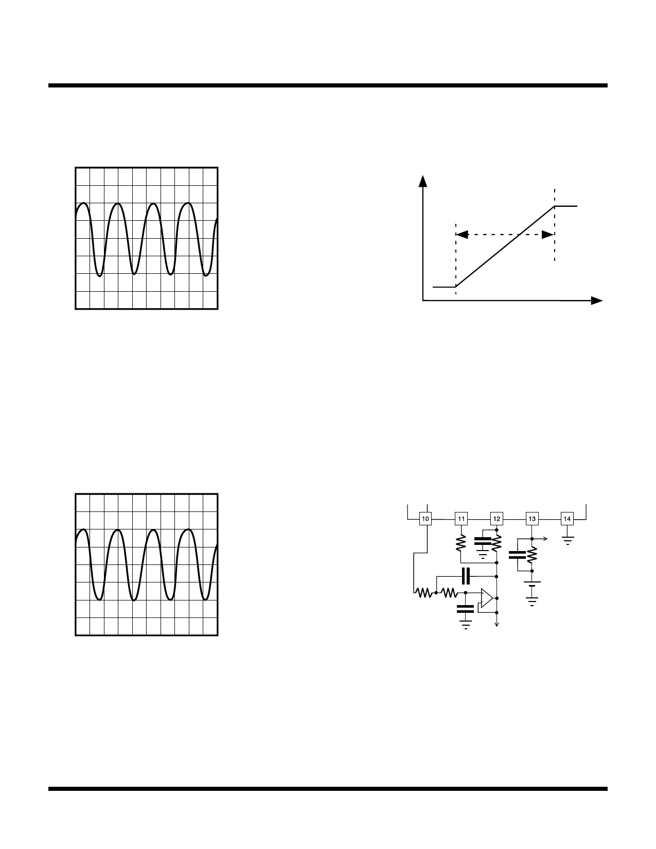
TK14551V
CIRCUIT DESCRIPTION
Figure 4 shows the AM demodulated waveform.
RSSI-OUT (V)
Operating Condition:
V = 3 V, fin = 40 MHz,
CC
fm = 2 MHz, Mod = ±80%,
VIN = -40 dBm
50 mV/div
0.2 µs/div
AM can be
demodulated
inside of linear
range
RF INPUT - LEVEL (dBu)
FIGURE 4 -AM DEMODULATED WAVEFORM
If it is necessary to improve the distortion of the AM demodulated waveform of logarithmic detection, connect a low pass
filter to the RSSI buffer amplifier output. Figure 5 shows the AM demodulated waveform with a low pass filter inserted.
Operating Condition:
VCC = 3 V, fin = 40 MHz,
fm = 2 MHz, Mod = ±80%,
V = -40 dBm
IN
50 mV/div
0.2 µs/div
FIGURE 5
TEST CIRCUIT
3k C
33 pF
3k
10 pF
2.2 k 2.2 k
15 pF
fc = 3 MHz
1k
COMP VCC
Page 22
January 2000 TOKO, Inc.
Share Link: 