TLP705(2004) Ver la hoja de datos (PDF) - Toshiba
Número de pieza
componentes Descripción
Fabricante
TLP705 Datasheet PDF : 6 Pages
| |||
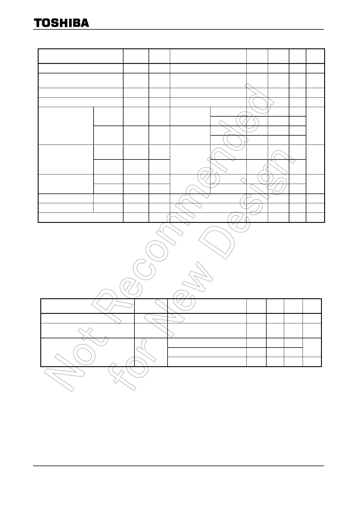
TLP705
Switching Characteristics (Ta = −40 to 100°C, unless otherwise specified)
Characteristics
Symbol
Test
Circuit
Test Condition
Min
L→H
tpLH
Propagation delay time
H→L
tpHL
L→H
tpLH
Propagation delay time
H→L
tpHL
Propagation delay difference
between any two parts or channels
tpsk
Pulse Width Distortion
PWD
(tpHL-tpLH)
VCC = 20 V
Rg = 30 Ω
7 Cg = 1 nF
f=250kHz
Duty Cycle
=50%
Ta= 25℃
IF = 0→10 mA
70
Ta= 25 ℃
IF = 10→ 0 mA
70
Ta= -40 to100℃
IF = 0→10 mA
50
Ta= -40 to100℃
IF = 10→0 mA
50
Ta= -40 to100℃
IF = 10 mA
-90
Ta= -40 to100℃
IF = 10 mA
-65
Typ.* Max Unit
95
170
105 170
200
200
ns
90
65
Output rise time (10-90%)
tr
IF = 0 → 10 mA
Output fall time (90-10%)
Common mode transient immunity
at hight level output
Common mode transient immunity
at low level output
tf
CMH
CML
VCM =
8 1000Vp-p
VCC = 20 V
Ta = 25°C
IF = 10 → 0 mA
IF = 10 mA
VO (min) = 16 V
−10000
IF = 0 mA
VO (max) = 1 V
10000
V/µs
*: All typical values are at Ta = 25°C
Test Circuit 1: IOPH
1
IF
6
V6-5
A IOPH
VCC
3
4
Test Circuit 2: IOPL
1
6
IOPL
A
VCC
V5-4
3
4
Test Circuit 3: VOH
1
6 VOH
V
IF
VCC
3
4
Test Circuit 4: VOL
1
6
VF
3
VOL
V
4
VCC
4
2004-10-19
Share Link: 