WM8940CGEFL(2011) Ver la hoja de datos (PDF) - Wolfson Microelectronics plc
Número de pieza
componentes Descripción
Fabricante
WM8940CGEFL Datasheet PDF : 91 Pages
| |||
Production Data
WM8940
Figure 6 Microphone Input PGA Circuit (switch positions shown are for differential mic
input)
REGISTER
ADDRESS
R44
Input Control
BIT
LABEL
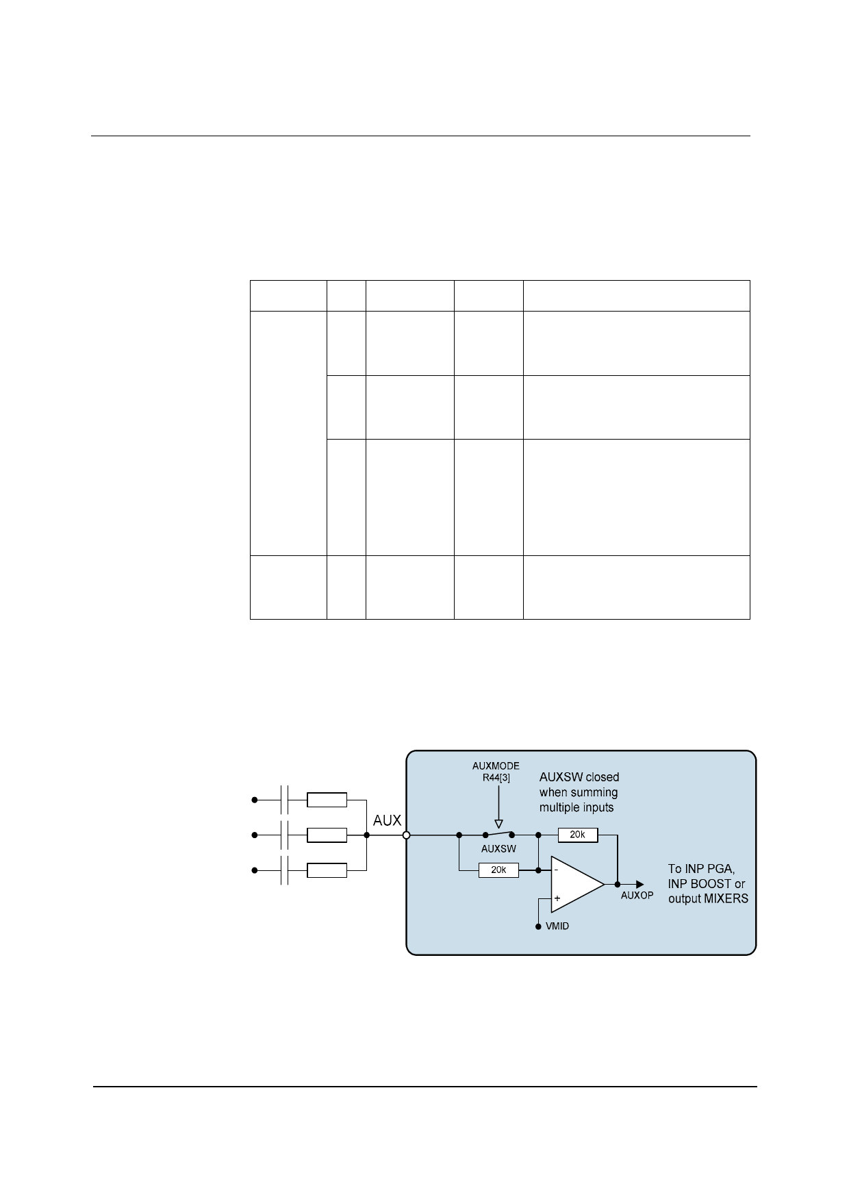
2 AUX2INPPGA
DEFAULT
0
1 MICN2INPPGA 1
0 MICP2INPPGA 0
Table 2 Input Control
DESCRIPTION
Select AUX amplifier output as input PGA
signal source.
0=AUX not connected to input PGA
1=AUX connected to input PGA amplifier
negative terminal.
Connect MICN to input PGA negative
terminal.
0=MICN not connected to input PGA
1=MICN connected to input PGA amplifier
negative terminal.
Connect input PGA amplifier positive
terminal to MICP or VMID.
0 = input PGA amplifier positive terminal
connected to VMID
1 = input PGA amplifier positive terminal
connected to MICP through variable resistor
string
The input PGA is enabled by the IPPGAEN register bit.
REGISTER
ADDRESS
R2
Power
Management 2
BIT
2
LABEL
INPPGAEN
Table 3 Input PGA Enable Control
DEFAULT
DESCRIPTION
0
Input microphone PGA enable
0 = disabled
1 = enabled
w
PD, Rev 4.3, November 2011
19
Share Link: 