W971GG8KB-25 Ver la hoja de datos (PDF) - Winbond
Número de pieza
componentes Descripción
Fabricante
W971GG8KB-25 Datasheet PDF : 87 Pages
| |||
W971GG8KB
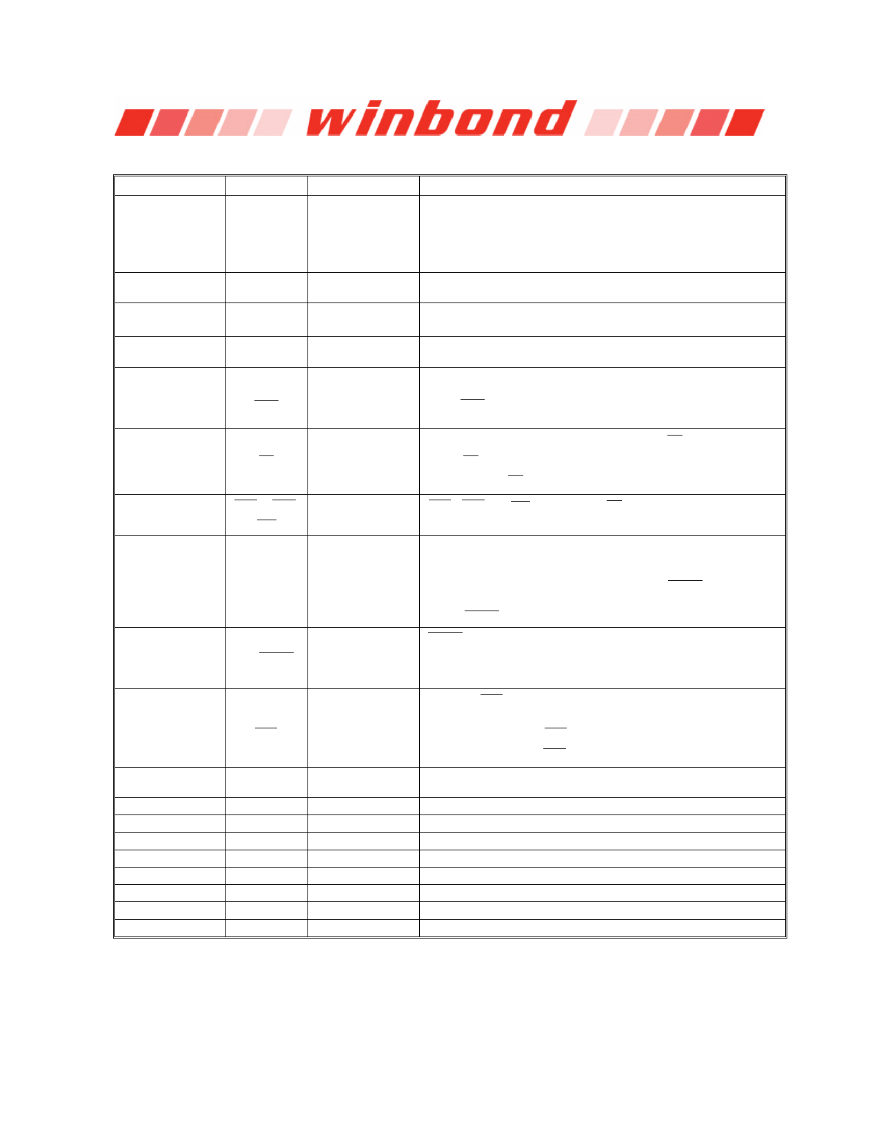
6. BALL DESCRIPTION
BALL NUMBER SYMBOL
H8,H3,H7,J2,J8,J3,
J7,K2,K8,K3,H2,K7,
L2,L8
A0−A13
G2,G3,G1
BA0−BA2
C8,C2,D7,D3,D1,D9,
B1,B9
DQ0−DQ7
F9
ODT
B7,A8
DQS,
DQS
FUNCTION
Address
Bank Select
Data Input
/ Output
On Die Termination
Control
Data Strobe /
Differential Read
Data Strobe
DESCRIPTION
Provide the row address for active commands, and the column
address and Auto-precharge bit for Read/Write commands to select
one location out of the memory array in the respective bank.
Row address: A0−A13.
Column address: A0−A9. (A10 is used for Auto-precharge)
BA0−BA2 define to which bank an ACTIVE, READ, WRITE or
PRECHARGE command is being applied.
Bi-directional data bus.
ODT (registered HIGH) enables termination resistance internal to the
DDR2 SDRAM.
Output with read data, input with write data for source synchronous
operation. Edge-aligned with read data, center-aligned with write
data. DQS is only used when differential data strobe mode is
enabled via the control bit at EMR (1) [A10] = 0.
All commands are masked when CS is registered
G8
CS
Chip Select
HIGH. CS provides for external rank selection on systems with
multiple ranks. CS is considered part of the command code.
F7,G7,F3
B3
A2
RAS , CAS ,
WE
DM/RDQS
Command Inputs
Input Data Mask/
Read Data Strobe
RAS , CAS and WE (along with CS ) define the command being
entered.
DM is an input mask signal for write data. Input data is masked when
DM is sampled HIGH coincident with that input data during a Write
access. DM is sampled on both edges of DQS. The DM loading
matches the DQ and DQS loading. RDQS/ RDQS are used as
strobe signals during reads is enabled by EMR (1) [A11] = 1. If
RDQS/ RDQS is enabled, the DM function is disabled.
NU/ RDQS
Not Use/Differential
Read Data Strobe
RDQS is only used when RDQS is enabled and differential data
strobe mode is enabled. If differential data strobe mode is disabled
via the control bit at EMR (1) [A10] = 1, then ball A2 and A8 are not
used.
E8,F8
F2
J2
A1,E9,H9,L1
A3,E3,J1,K9
A9,C1,C3,C7,C9
A7,B2,B8,D2,D8
L3,L7
E1
E7
CLK,
CLK
CKE
VREF
VDD
VSS
VDDQ
VSSQ
NC
VDDL
VSSDL
Differential Clock
Inputs
Clock Enable
Reference Voltage
Power Supply
Ground
DQ Power Supply
DQ Ground
No Connection
DLL Power Supply
DLL Ground
CLK and CLK are differential clock inputs. All address and control
input signals are sampled on the crossing of the positive edge of CLK
and negative edge of CLK . Output (read) data is referenced to the
crossings of CLK and CLK (both directions of crossing).
CKE (registered HIGH) activates and CKE (registered LOW)
deactivates clocking circuitry on the DDR2 SDRAM.
VREF is reference voltage for inputs.
Power Supply: 1.8V ± 0.1V.
Ground.
DQ Power Supply: 1.8V ± 0.1V.
DQ Ground. Isolated on the device for improved noise immunity.
No connection.
DLL Power Supply: 1.8V ± 0.1V.
DLL Ground.
Publication Release Date: Sep. 11, 2013
-7-
Revision A02
Share Link: 