M54HCT74F1R Ver la hoja de datos (PDF) - STMicroelectronics
Número de pieza
componentes Descripción
Fabricante
M54HCT74F1R Datasheet PDF : 11 Pages
| |||
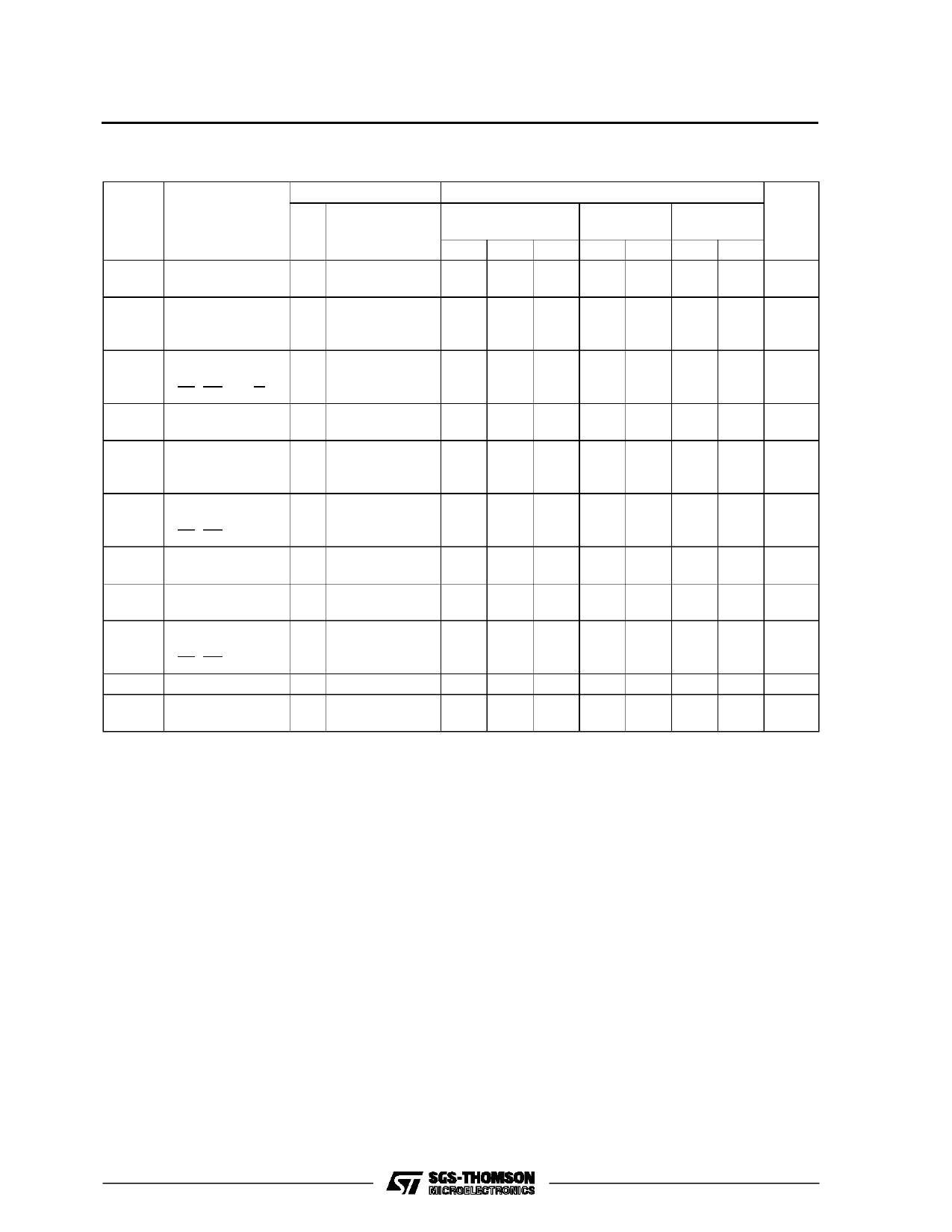
M54/M74HCT74
AC ELECTRICAL CHARACTERISTICS (CL = 50 pF, Input tr = tf = 6 ns)
Symbol
Parameter
Test Conditions
VCC
(V)
TA = 25 oC
54HC and 74HC
Value
-40 to 85 oC -55 to 125 oC Unit
74HC
54HC
Min. Typ. Max. Min. Max. Min. Max.
tTLH Output Transition 4.5
tTHL Time
tPLH Propagation
4.5
tPHL Delay Time
(CLOCK - Q)
8
15
19
22
ns
21 33
41
50
ns
tPLH Propagation
4.5
tPHL Delay Time
(CL, PR - Q, Q)
18 30
38
45
ns
fMAX Maximum Clock 4.5
Frequency
27 48
22
18
MHz
tW(H) Minimum Pulse 4.5
tW(L) Width
(CLOCK)
6
15
19
23
ns
tW(L) Minimum Pulse 4.5
Width
(CL, PR)
8
15
19
23
ns
ts
Minimum Set-up 4.5
Time
7
15
19
23
ns
th
Minimum Hold
4.5
Time
0
0
0
ns
tREM Minimum
4.5
Removal Time
(CL, PR)
1
5
5
6
5
8
ns
CIN Input Capacitance
5
10
10
10 pF
CPD (*) Power Dissipation
32
Capacitance
pF
(*) CPD is defined as the value of the IC’s internal equivalent capacitance which is calculated from the operating current consumption without load.
(Refer to Test Circuit). Average operting current can be obtained by the following equation. ICC(opr) = CPD •VCC •fIN + ICC/2 (per FLIP/FLOP)
5/11
Share Link: 