BT151 Ver la hoja de datos (PDF) - Unisonic Technologies
Número de pieza
componentes Descripción
Fabricante
BT151 Datasheet PDF : 5 Pages
| |||
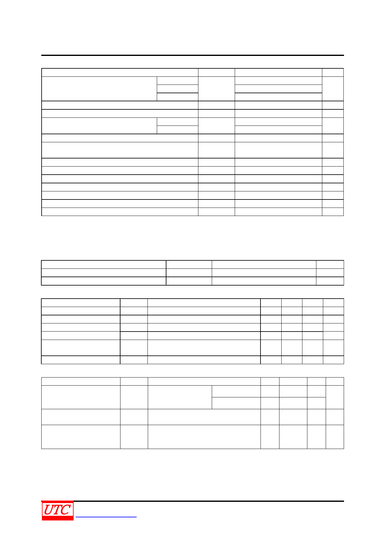
BT151
SCR
ABSOLUTE MAXIMUM RATING
PARAMETER
SYMBOL
RATINGS
UNIT
BT151-5
500 (Note 1)
Repetitive Peak Off-State Voltages
BT151-6
VDRM, VRRM
650 (Note 1)
V
BT151-8
800
Average On-State Current (half sine wave; Tmb ≤109°C)
RMS on-State Current (all conduction angles)
Non-Repetitive Peak On-State Current
t = 10 ms
(half sine wave; TJ = 25 °C prior to surge) t = 8.3 ms
I2t for Fusing (t = 10 ms)
IT(AV)
IT(RMS)
ITSM
I2t
7.5
A
12
A
100
A
110
50
A2s
Repetitive Rate of Rise of On-State Current After Triggering
(ITM = 20 A; IG = 50 mA; dIG /dt = 50 mA/μs)
dIT /dt
50
A/μs
Peak Gate Current
IGM
2
A
Peak Gate Voltage
VGM
5
V
Peak Reverse Gate Voltage
VRGM
5
V
Peak Gate Power
PGM
5
W
Average Gate Power (Over any 20 ms period)
PG(AV)
0.5
W
Storage Temperature
Tstg
-40 ~150
°C
Operating Junction Temperature
TJ
125
°C
Note: 1. Although not recommended, off-state voltages up to 800V may be applied without damage, but the thyristor
may switch to the on-state. The rate of rise of current should not exceed 15A/μs.
2. Absolute maximum ratings are those values beyond which the device could be permanently damaged.
Absolute maximum ratings are stress ratings only and functional device operation is not implied.
THERMAL DATA
PARAMETER
Junction to Mounting Base
Junction to Ambient
SYMBOL
θJMb
θJA
RATINGS
1.3
60
UNIT
K/W
K/W
STATIC CHARACTERISTICS (TJ=25℃,unless otherwise stated)
PARAMETER
SYMBOL
CONDITIONS
Gate Trigger Current
IGT VD = 12 V, IT = 0.1 A
Latching Current
IL VD = 12 V, IGT = 0.1 A
Holding Current
IH VD = 12 V, IGT = 0.1 A
On-State Voltage
VT IT = 23 A
Gate Trigger Voltage
VGT
VD = 12 V, IT = 0.1 A
VD = VDRM(max) , IT = 0.1 A, TJ = 125 °C
Off-State Leakage Current
ID , IR VD = VDRM(max) , VR = VRRM(max) ,TJ = 125°C
MIN
0.25
TYP
2
10
7
1.4
0.6
0.4
0.1
MAX
15
40
20
1.75
1.5
UNIT
mA
mA
mA
V
V
0.5 mA
DYNAMIC CHARACTERISTICS(TJ=25℃,unless otherwise stated)
PARAMETER
SYMBOL
CONDITIONS
MIN
Critical Rate of Rise of
Off-State Voltage
VDM = 67% VDRM(max), Gate open circuit 50
dVD /dt TJ = 125 °C,
exponential waveform; RGK = 100Ω
200
Gate Controlled Turn-on
Time
tGT
ITM = 40 A, VD = VDRM(max), IG = 0.1 A,
dIG /dt = 5 A/μs
Circuit Commutated
Turn-off tIme
VD = 67% VDRM(max), TJ = 125°C;
tQ ITM = 20 A, VR = 25 V, dITM /dt = 30 A/μs,
dVD /dt = 50 V/μs, RGK = 100 Ω
TYP
130
1000
2
70
MAX UNIT
V/μs
μs
μs
UNISONIC TECHNOLOGIES CO., LTD
www.unisonic.com.tw
2 of 5
QW-R301-017,C
Share Link: 